
WELCOME
Thanks for purchasing Grandstream Network IPVT10 full-HD conferencing system.
This document introduces the IPVT10 installation process and usage instructions, including environment setup, start meetings and operations, scheduling meetings, etc.
For more information about IPVT10 and IPVideoTalk service, please visit the product page at: http://www.ipvideotalk.com
This manual applies to IPVT10 equipment administrators.
PRODUCT OVERVIEW
IPVT10 is an On-Premise Video Conferencing Server designed for enterprises seeking a powerful and secure video conferencing solution. It offers one easy-to-use platform that combines all aspects of enterprise video conferencing applications, including room and web-based options and conferencing management. IPVT10 provides a centralized solution to manage an entire business’s conferencing needs through one single server and interface. This On-Premise Video Conferencing Server is ideal for internal conferencing solutions among small and medium-sized enterprises, especially those with multiple locations, for example, communication between headquarters and multiple branch offices. It is also ideal for organizations that need to communicate with remote employees and those who perform remote training and/or education through video conferencing.
Feature Highlights
The following tables contain the major features of the IPVT10:
 IPVT10 |
|
Table 1: IPVT10 Features in a Glance
IPVT10 Technical Specifications
The following table resumes all the technical specifications including the protocols/standards supported, server module, audio/video features, MCU functional features, meeting, and device management for IPVT10.
Application Functions | Built-in Video MCU, SIP Registrar Server, H.323 Gateway, NAT Traversal Server, Enterprise Collaboration Server, Contacts Manager, Recording/Storage Server, WebRTC Server. |
Conference Capacity | Up to 120-way 1080p H.264 video/audio MCU. Up to 300 participants (aggregate) with 2-way audio and 1-way 1080p H.264 video streaming. Up to 10 meetings of more than three parties or 50 meetings of two parties without WebRTC client. |
Video Support | H.264 BP/MP/HP with up to 1080p resolution and 6Mbps bit rate per stream. |
Audio Support | Opus, G.722, G.711a/u, up to 48KHz wide-band audio mixing. |
Network Jitter Resilience | Advanced anti-jitter algorithms to sustain high-quality audio/video against up to 30% packet loss. Smart adaptation to dynamically adjust bandwidth between 64Kbps and 6Mbps based on thenetwork condition. |
Security | Support HTTPS and WSS/DTLS-SRTP encryption for WebRTC, and TLS/SRTP encryption for SIP |
Video Display | Support 2×2/3×3/4×4/5×5/6×6/7×7 Tile Video Layout, or 1 Primary + N Secondary (up to 7 secondary) Video Layout. 1 meeting supports up to 3 meeting layouts and also supports assigningthe viewing permission for other participants. |
Active Speaker Highlight | Automated active speaker detection and highlight. |
Meeting Management | Support Immediate or Scheduled Meetings/Webinars, multiple hosts/panelists, audio/video ON/OFF control. Desktop/application sharing, group or private chat, Q&A, meeting banners/captions, sending pictures and files, forced attendee Mute/Camera-Off/Exit by the host. Customizable content for meeting invitation/registration/reminder/post-meeting reports and follow-up. |
Live Streaming | Support live streaming with Facebook and Youtube, and other live streaming platforms via RTMP push. |
Supported Devices | Grandstream GVC series video conference systems, GXV series video phones, PC/Mac using WebRTC browsers, Android/iOS-based mobile devices using Grandstream IPVideoTalk mobile APP. Audio calling from PSTN SIP trunk or SIP-based IPPBX, 3rd party SIP-basedvideo conference systems and video phones. |
Meeting Records | Support up to 500GB local storage of audio/video/chats recording, meeting reports, etc. Support remote mounting NFS extended disk. |
Deployment Scalability | Scalable architecture to support multi-server configuration with load-balancing and redundancy for large deployments. |
Multi-language | English, German, French, Spanish, Chinese, Japanese, Arabic, etc. |
Power Supply | Redundant 550W power supplies. |
Network Interfaces | 2x Gigabit network ports, 1x RJ45 IPMI network port. |
Auxiliary Interfaces | 3x USB 3.0 ports, 3x USB 2.0 ports, and 1x VGA port. |
Physical Dimension | 430mm (W) x 650mm (L) x 88mm (H), 2U rack design suitable for 19-inch cabinet and guide rail. |
Temperature & Humidity | Operations 0°C to 45°C, Humidity 10% ~ 90% non-condensing. |
Compliance | FCC, CE, RCM. |
INSTALLING IPVT10
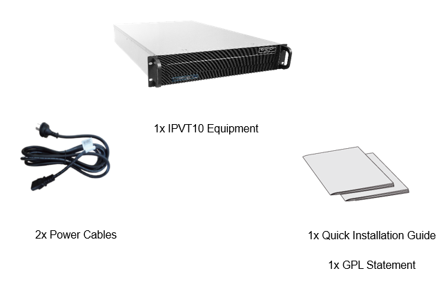
Equipment Package Content
Installation Process
Users need to follow the steps described in the table below to correctly complete the installation of the IPVT10:
Index | Steps | Instructions |
| 1 | Equipment Inspection | Open the package, check the equipment and accessories, and inspect the hardware structure of the IPVT10. |
| 2 | Install to Cabinet (Optional) | Install IPVT10 to the cabinet |
| 3 | Connect to Network | Connect to the network with the Ethernet cable. |
| 4 | Connect to the power supply | Connect to the power supply with the power adapter. |
| 5 | Power On | Inspect the running status of the equipment. |
Equipment Inspection
Users need to open the package and check the equipment and parts to ensure the integrity and availability of the equipment.
Equipment Appearance
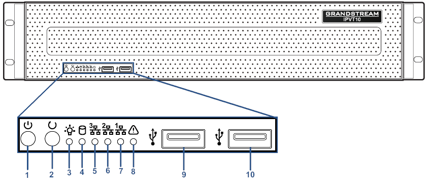
- IPVT Front Panel
NO. | Name | Description |
1 | Equipment Switch | When the equipment is not running, press the switch to turn on the equipment, and when the equipment is running normally, long-press the switch (5 seconds) will turn off the equipment. |
2 | Reboot Switch | When the equipment is running normally, pressing this switch will reboot the equipment. |
3 | Power Indicator |
|
4 | Hard Disk Indicator |
|
5 | Network Connection Indicator |
|
6 | Ethernet Interface 1 Indicator |
|
7 | Ethernet Interface 2 Indicator |
|
8 | Failure Indicator |
|
9 | USB Interface 1 | USB 2.0. Users could connect with a mouse or keyboard. |
| 10 | USB Interface 2 | USB 3.0. Users could connect with a mouse or keyboard. |
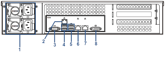
- IPVT Back Panel
NO. | Name | Description |
1 | Power Supply Interfaces | Two Power Supply Interfaces are available on the IPVT10, the users need to connect the power cables to the two interfaces to keep powering the device and to avoid shutting it down in case one of the power supply is defective. |
2 | IPMI Interface | Intelligent Platform Management Interface. |
3 | COM Interface | RS-232 serial communication interface |
4 | USB Interfaces 3 and 4 | USB 2.0. Users could connect with a mouse or keyboard. |
5 | USB Interfaces 5 and 6 | USB 3.0. Users could connect with a mouse or keyboard. |
6 | 1000M Ethernet Interface 1 | Connect to the network LAN port, connect with a PC to access the configuration page of the server |
7 | 1000M Ethernet Interface 2 | Connect to the network LAN port |
8 | VGA Interface | Connect to a VGA equipment |
Equipment Specifications
Name | Description |
Power Supply | 550W. (Redundancy PSU) |
Applicable Cabinet | 2U Rackmount Design, and it supports 19” cabinets and rails. |
Equipment Size | Base Equipment Size: Height 88mm * Width 430mm * Depth 650mm. |
USB Interfaces |
3x USB 3.0 (2 rear, 2 via header).
|
LAN Interfaces | 2x RJ45 Gigabit Ethernet LAN ports. 1x RJ45 Dedicated IPMI LAN port. |
Display Interfaces | 1 x VGA port. |
Operating Temperature | 0°C to 45°C |
Mounting IPVT10 Equipment to Cabinet
Users can install the IPVT10 in a 19-inch cabinet that conforms to the IEC (International Electro-Technical Commission) 60297 standards.
- The IPVT10 server is heavy and we suggest carrying it with two people at least.
- If the cabinet has been installed, then suggest a space of at least “2U” (1U=44.45mm) to be reserved.
- Users can select the regular rail for installation or optional installation.
Example:
Rail structure: It is composed of inner rail, outer rail, and rail holder. The inner rail and the outer rail are connected, and they cannot be split. They are mounted on the cabinet through the rail holder; the inner rail is installed on the server equipment (Rails and Rail Holders are not included within the package contents).
Steps:
- Remove the rail holder and the rails by loosening the 4 screws first, and then removing the front and back rail holders.
- Install the inner rail to the server case. Pull the inner rail out of the rail until it cannot be pulled.
- Fix the inner rail with 2 screws to the server case. Fit the smooth surface of the inner rail to the side of the server case and match the screw holes on the inner rail with the screw holes on the server case. Hold the inner rail tightly against the server case and tighten with the screws.
- Repeat steps 1 to 3 to install the other inner rail on the other side of the server case.
- Install the rail holder to the cabinet. Make sure the installation position of the front rail holder on the cabinet, align the two fixing holes between the rail holder and the cabinet corner and tighten the screws. Then, according to the depth of the cabinet (the depth of the cabinet is 650mm), adjust the back-rail holder properly, align the two fixing holes between the back-rail holder and the cabinet corner at the back of the cabinet, tighten the screws. (Note: Please make sure that the front and back rail holders are horizontal).
- Repeat the above steps to install the other front and back rail holders in the cabinet. (Note: Please make sure that the left and right-side rails are horizontal).
- Lift the server up and close to the cabinet so that the back of the server faces the front of the cabinet. Insert the inner rails on the two sides of the server into the front and back rail holders on the cabinet, align the fixing holes and tighten the screws.
- When the installation is completed, push the server into the cabinet.
Connecting IPVT10 Server
Connecting Network Cables
To ensure to run IPVT10 Server properly, users need to connect the server to a Gigabit switch.
Please connect IPVT10 Server according to the following procedures:
- Connect the RJ45 Ethernet cable with the Ethernet Interface 1.
- Connect the RJ45 Ethernet cable with the Gigabit switch.
- Repeat steps “1” and “2” to connect with Ethernet interface 2.


Connecting Power Supply cables
IPVT10 only supports AC power supply, users can connect the two power supply cables following the steps below:
- Connect the standard power supply cable with the equipment.
- Plug the power supply into the AC power supply.
- Repeat steps “1” and “2” to connect the second power supply cable.
Powering on IPVT10
Before powering on the equipment, users need to ensure that the equipment meets the following conditions:
- If the equipment is installed in a cabinet, please ensure that the screws are fixed, and the equipment has enough space for heat dissipation.
- The connections of the cables on the equipment are normal.
- The input power and current are within the working range of the equipment.
- The distance between the power cable and the Ethernet cable outside the cabinet must be greater than 30 mm.
Once the previous conditions are checked, the users can power up the IPVT10 Server. To make the equipment run properly, users need to press the equipment switch in the front panel of the server to power on the equipment. The indicator will turn to solid green.
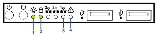
After the equipment is turned on, please check the following indicators to make sure the equipment is working properly.
NO. | Name | Description |
1 | Power Indicator |
|
2 | Hard Disk Indicator |
|
3 | Network Connection Indicator |
|
4 | Failure Indicator |
|
CONFIGURING IPVT10
Descriptions of Meeting Capacity
Table 8: IPVT10 Server Meetings Performance
Current Meeting Number | Max Video Feeds | Max Participants | Descriptions |
1 | 120 | 300 (Dual NICs) 200 (Single NIC) |
|
2 | 120 | 200 |
|
4 | 120 | 160 |
|
6 | 120 | 140 |
|
8 | 120 | 130 |
|
10 | 120 | 120 |
|
50 | 100 | 100 |
|
Configuration Instructions
Users could manage and configure the IPVT10 configuration information by logging in to the Web UI of the IPVT10 server via a browser of the computer.
First-time Configuration
Users need to properly follow the steps listed in the table below at the first login.
Table 9: Steps for First-time Configuration
Steps | Description |
Configure Service IP Address | According to the configuration of the network solution, configure the service IP address. Support to configure dual network adapters, NAT, and routing rules. |
Configure SMTP Mailbox | The SMTP mailbox is used as a sender to send the meetings invitation Emails, meetings notification Emails, etc. Users could configure Enterprise email as SMTP Mailbox. |
Configure Conference Management Platform Information | This is used to configure the login account, enterprise information, default language, default time zone, and other information on the platform. |
Configuration Parameters Modification
After the deployment is completed, users can modify the configuration parameters.
Parameters | Description |
Update Service IP Address | Please configure this parameter carefully:
|
Update SMTP Mailbox | When the SMTP Mailbox is updated, it will take effect immediately, and does not affect other data. |
Update Conference Management Platform Information | When the Conference Management Platform information is updated, it will take effect immediately, and does not affect other data. |
Upgrading Service
If users need to upgrade the software system in the IPVT10, users can log into the Conference Management Platform and upgrade the service.
- Please download the system installation package from Grandstream’s Official Website.
- During the upgrading process, the system service will be suspended.
- The upgrading service will not affect the data in the database server and the original configuration.
Factory Reset
Users need to be careful about factory reset operations. When users start to factory reset the device, it will be restored to the factory default settings, and all the data will be erased, including user’s data and meetings data.
Log in to the Configuration Page
IPVT10 has a built-in Web Configuration Management Platform, and users could log in to the platform via a browser by entering the Web Management Platform IP Address or via IPVideoTalk Portal to manage the configuration of the IPVT10.
Accessing the Configuration Page directly via a Browser
Users need to have a computer that is on the same VLAN network as the server, to be able to log into the server’s web management platform.
Table 11: Default Login Username and Password
Parameters | Description |
Web Management Platform IP Address | 192.168.88.88 |
Admin User Name | admin |
Admin Default Password |
|
Users need to follow the steps below to log in to IPVT10 Web UI:
- Please make sure that the IP address of the computer is at the same network segment as the servers. If not, go to the “Network” configuration page of the computer to set up the network segment to be the same as IPVT10 servers.
- Enter the default IP address (http://192.168.88.88) of the equipment in the browser of the PC, and press “Enter” to access the configuration page, as the screenshot shows below:
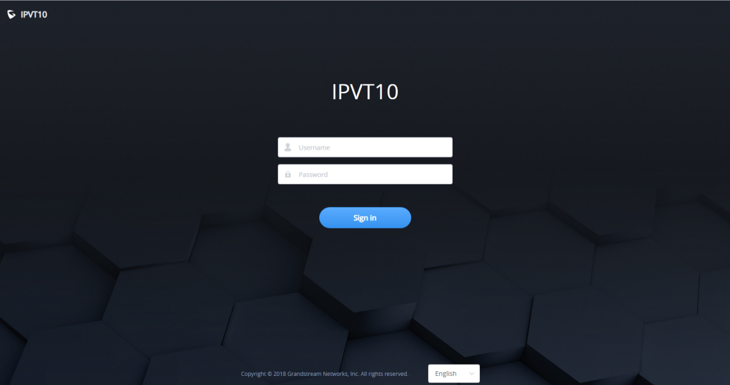
3. Input login user name and password (If there is no sticker on the device with the random default password, the default password of the device is “change_me”; If there is a sticker on the device with the random default password, use the password on the sticker as the default login password)
4. For security reasons, Users will be asked to change the default password and choose another one before logging in.
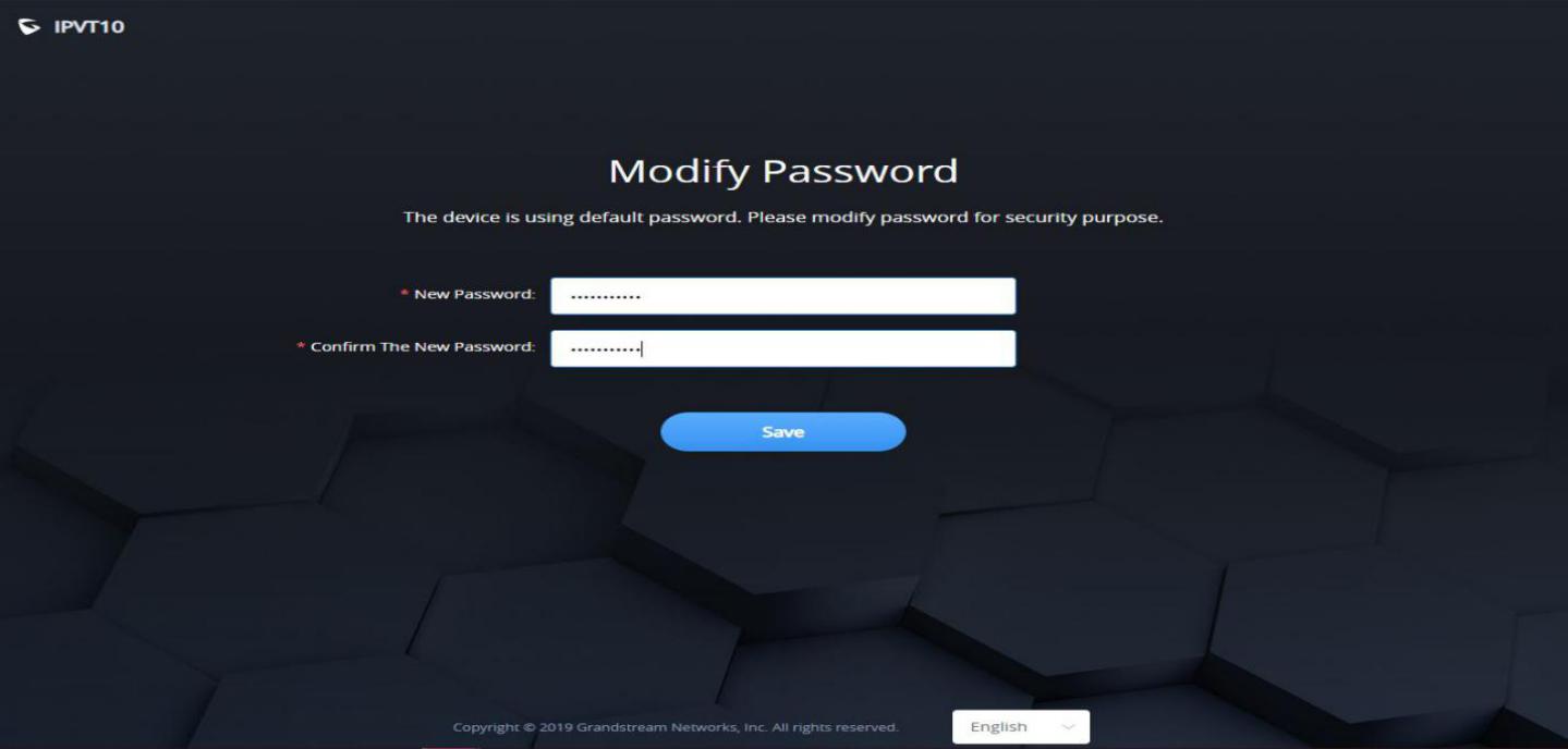
5. (Optional) Users could select the language on the list at the bottom of the configuration page.
6. Click to log in to the configuration page.
If there is an IP conflict, users can connect the PC directly to the server via an Ethernet cable for configuration purposes. Follow the steps below:
- Unplug the Ethernet cable from the Ethernet Port 1 on the IPVT equipment (the first cable interface from left to right in the figure).
- Then, connect the Ethernet Port 1 and a PC with an Ethernet cable as shown in the figure:
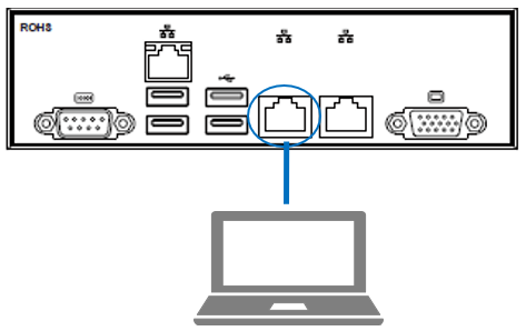
3. Enter the default IP address (http://192.168.88.88) of the IPVT10 equipment in the browser of the computer, and press “Enter” to access the configuration page.
4. Input login username and password
5. (Optional) Users could select the language on the list at the bottom of the configuration page.
6. Click to log in to the configuration page.
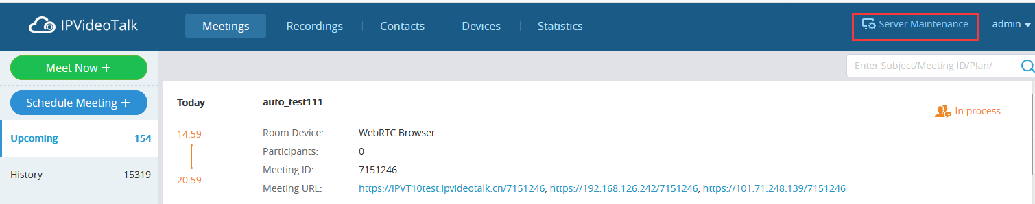
Accessing the Configuration Page via IPVideoTalk Portal
Users could log into IPVT10 Web Interface via IPVideoTalk Portal by clicking on “Maintenance”, as per the following figure:
Update Login Password
When users first-time login to IPVT10 Web Deployment Platform, it is recommended to modify the password of the administrator account to ensure the security of the system. Refer to the following steps:
- Log in to the Web page of IPVT10.
- Click on the option “Advanced Settings 🡪 Modify Password” to access the configuration.
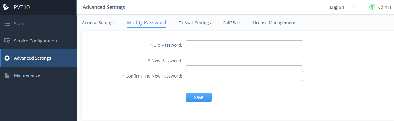
3. Input “Original Password”, “New Password”, and “Confirm New Password”.
4. Click to save the configuration, and the system will prompt you to save successfully. If the original password is incorrect, or the new password format is incorrect, the corresponding error will be prompted.
Forgot Password
If users forgot the login password of IPVT10, users could reset the login password to the default password.
- Connect your PC to the Ethernet port 1 of the IPVT10 server directly or change the IP address of your PC to the same network segment as the IPVT10 server (192.168.88.xx), users could access the IPVT10 Web UI directly.
- Use the browser on your PC to access address “192.168.88.88/iforget” to open the login password reset page, as the screenshot shows below:
![IH[]YDFL3`O$TW[M_ROR)[Q](https://documentation.grandstream.com/wp-content/uploads/2021/12/ihydfl3odollartwm_rorq-1024x507.jpeg)
3. Users need to input the MAC address of the IPVT10 server and serial number on the login password reset page.
4. Click on “Reset”, and the login password will be reset to the default login password:
- If there is no sticker on the device with the random default password, the default password of the device is “change_me”.
- If there is a sticker on the device with the random default password, please use the password on the sticker as the default login password.
Setup Wizard
When users try to log in to the IPVT10 Web UI for the first time, users could follow the Setup Wizard to set up the IPVT10 server.
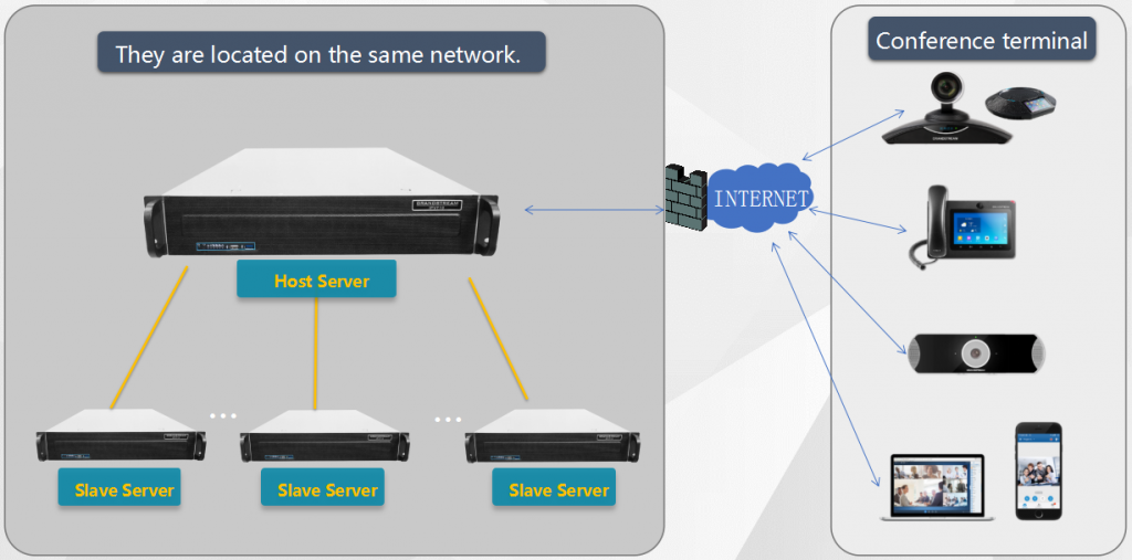
- Users need to select if they want to use the IPVT10 as the host server or slave server:
- Host Server: IPVT10 is used alone or used as a host server in a cluster. There is only one host server in a cluster, users cannot set multiple hosts in a cluster.
- Slave Server: IPVT10 is used as the slave server in a cluster with another host server and other slave servers. IPVT10 is used to extend the MCU conferencing function for the host server. The salve server does not need to configure N°5 – N°7 in the following configuration steps.
2. Network Settings: Users could configure the server IP address or domain name under this menu. For more details, please refer to section [Network Settings].
3. (Optional) Configure Service NAT Interfaces: Users could configure the custom server port under this menu. For more details, please, refer to section [Configure Service NAT Interfaces]
4. Time Configuration: The default setting is the server time is synchronized with the NTP server time. If the device is not connected to an external network, users need to set the time manually. For more details, please, refer to section [Time Configuration].
5. (Optional) Configure SIP Trunk Service Address: If users need to connect IPVT10 to an external SIP Trunk server, users need to set up the SIP Trunk Service under this menu. For more details, please, refer to section [Configure SIP Trunk Service Address].
6. (Optional) Configure SMTP Mailbox: It is recommended to fill in the SMTP Mailbox address. This is used to send invitation Emails to other meeting participants. For more details, please, refer to section [Configure SMTP Mailbox].
7. Configure Conference Management Platform Information: This page is used to set the login account information of the conference management platform. This platform is used to manage the devices and conferences. The Conference Management Platform is an independent platform compared with Setup Wizard. Please refer to section [Configure SMTP Mailbox
This Email box is used to send the meeting invitation Emails, meeting reminders, and other notifications as the Email sender. If users do not configure this Email box, the system cannot send Emails to inform the meeting participants.
Please, refer to the following steps:
- Login IPVT10 Web UI.
- Click on “Service Configuration” and configure the “SMTP Mailbox” options, as shown below:
3. Input the mailbox and configure the options below:
Parameters | Example |
SMTP Server | smtp.gmail.com |
SMTP Port | 465 |
SMTP Username | test@gmail.com |
SMTP Password | *** |
Mailbox Display Name | User’s enterprise name |
4. If the SMTP server is a self-signed certificate, you need to check “Ignore certificate“. Otherwise, the SMTP mailbox cannot send mail.
5. Before saving the SMTP mailbox configuration, users could click on the “Send a Test Email” button, and input the test email address in the pop-out window to receive the test email, then click on the “Send” button to send out the test email. Then, users could go to the test email box to check the test email. If the user could receive the test email, the SMTP mailbox has been configured correctly. Otherwise, the user needs to check the SMTP mailbox configuration on the Web UI.
6. Users could click to save the configuration and click on “Apply Now” to apply the entire configurations of this page to the server. When the deployment is complete, it will take effect immediately.
7. Cluster Settings: If users only use one IPVT10 server alone, users could ignore this setup step. If users use the IPVT10 in a cluster, this setup step is necessary. Please, refer to section [Cluster Settings]
Server Status
Users could log in to IPVT10 and check the server/conference status for the cluster host server like the screenshot shown below:
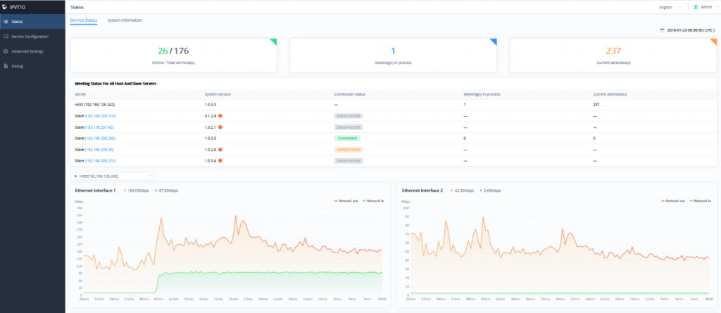
- Online / Total terminal(s): This information shows the number of the devices online currently, and the total number of devices.
- Meeting(s) in the process: This information shows the total number of meetings in progress currently. If the IPVT10 is a cluster host server, it will show the total number of ongoing meetings for all servers in the cluster.
- Current attendee(s): The information shows the total number of current participants attending the meeting. If the IPVT10 is a cluster host server, it shows the total number of current participants for all servers.
- Meeting status for all host and slave servers: The information shows the connection status of each slave server in the cluster, the number of conferences in progress, and the number of total meeting participants.
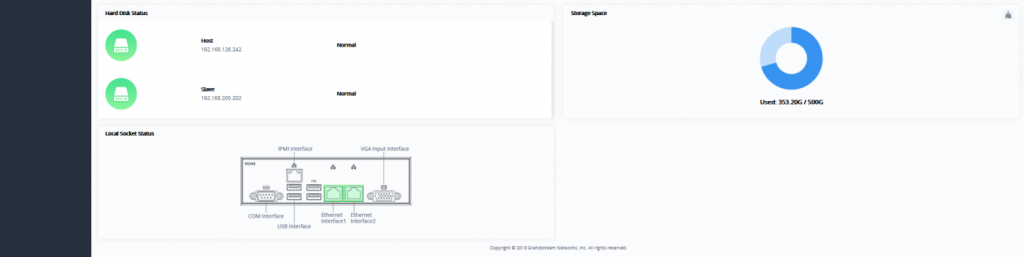
- Hard disk status: If an error occurs in the hard disk of the IPVT10 server, there will be a prompt indicating the user the error. It also displays the hard disk status of each slave server in the cluster.
- Storage Space: It shows the current used storage space and remaining storage space. Users could click on the button
 at the upper right corner to erase all files quickly in the storage space, including the recording files in the storage. If the server mounts NFS storage disk, it will show the storage space of the NFS disk. Users could click on the Clear button to clean up all data in the NFS disk.
 - Network Status: This information shows the network speed of the two Ethernet ports on the IPVT10 server.
- Interface Status: This information shows the current server’s socket usage status. If the socket usage status is detected as “In use”, it will display solid green.
Users could check the server/conference status for the cluster slave server as the screenshot shows below:
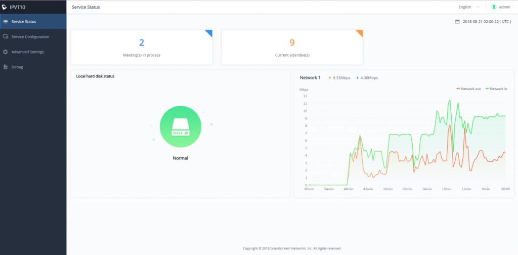
- Meeting(s) in process: This information shows the total number of meetings in progress currently. If the IPVT10 is a cluster host server, it will show the total number of ongoing meetings for all servers in the cluster.
- Current attendee(s): The information shows the total number of current participants attending the meeting. If the IPVT10 is a cluster host server, it shows the total number of current participants for all servers.
- Hard disk status: If an error occurs in the hard disk of the IPVT10 server, there will be a prompt indicating the user the error. It also displays the hard disk status of each slave server in the cluster.
- Network Status: This information shows the network speed of the Ethernet ports on the IPVT10 server. For slave servers, users only need to connect the Ethernet port 2 with the Internet.
- Interface Status: This information shows the current server’s socket usage status. If the socket usage status is detected as “In use”, it will display solid green.
Below are the explanations of each Hard Disk status icon:

| This icon represents the normal status of the Hard disk. |

| This icon means that the Hard disk status is abnormal, and the specific disk symbol will be displayed. |

| This icon means that the drive letter is rebuilt, and the specific disk symbol is displayed. After the reconstruction is successful, it will return to normal. |
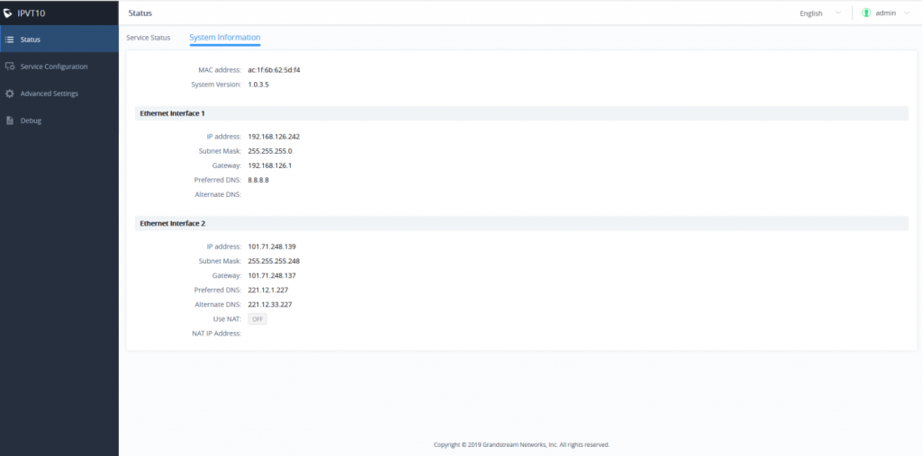
System Information
Users could view the system information of the server, such as MAC address, System version number, IP address, etc., as shown in the figure below:
Cluster Host Server Configuration
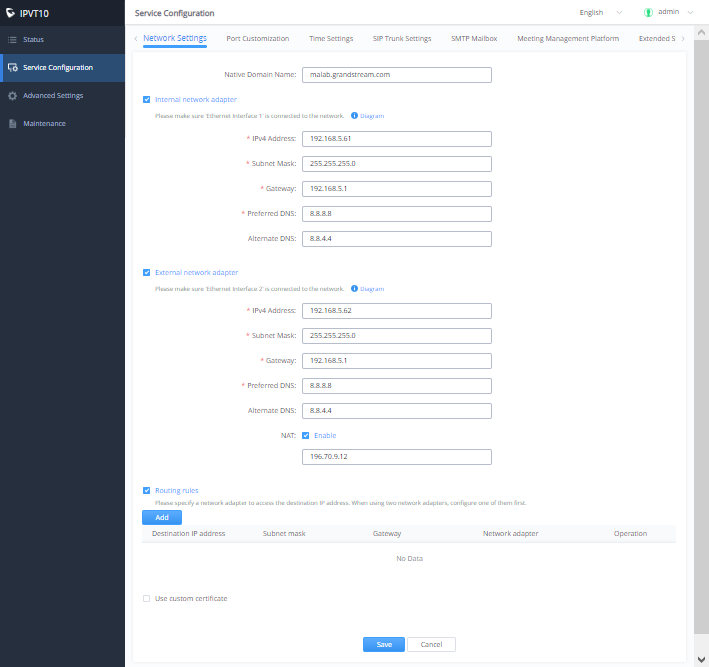
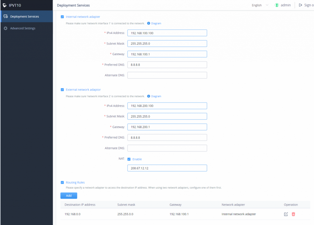
Network Settings
The IPVT10 server supports two network adapters that can be configured based on the actual requirements. There are 5 typical network deployment Scenarios:
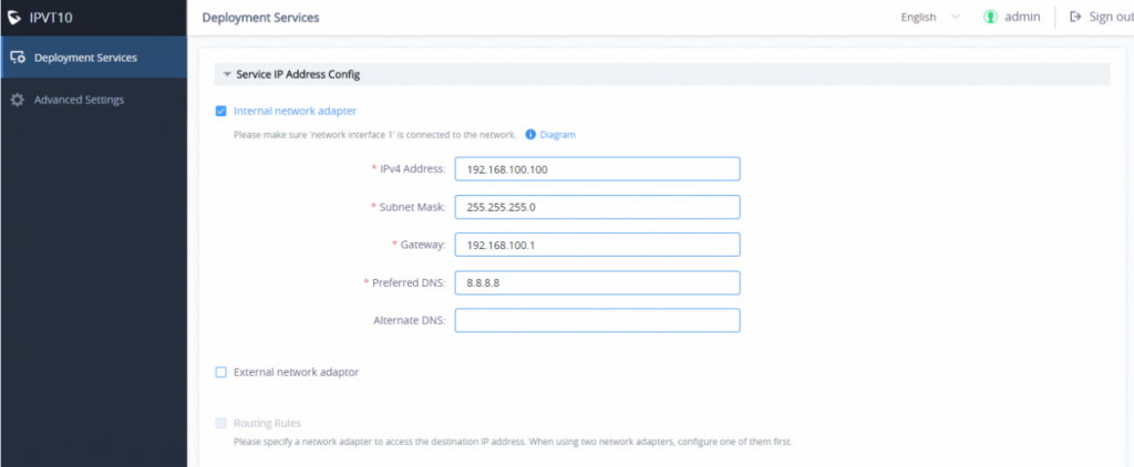
- Scenario 1: The server is deployed on the internal network. The end-users use the service only within the internal network. Users could only configure the internal network IP address.
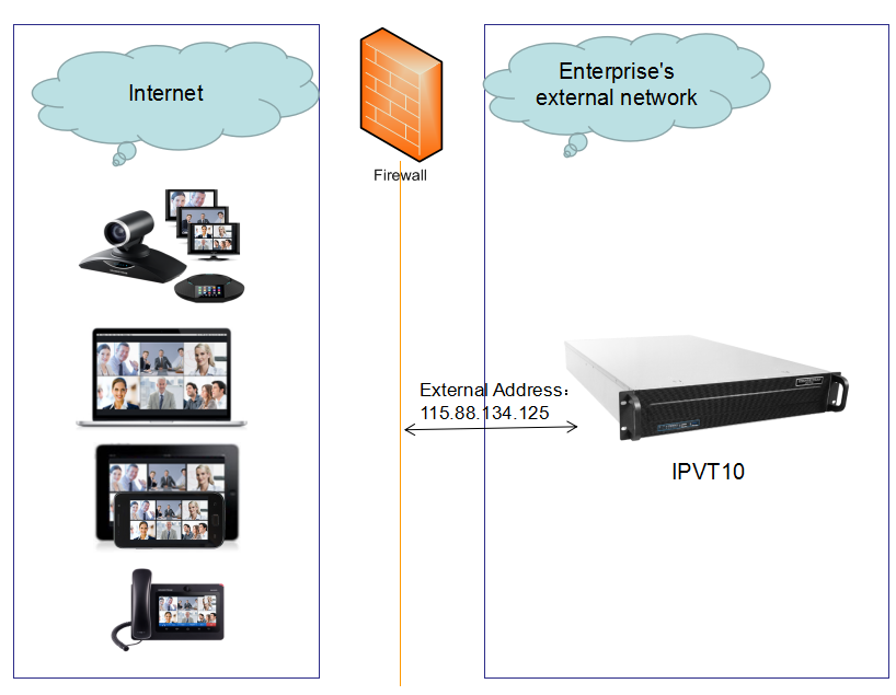
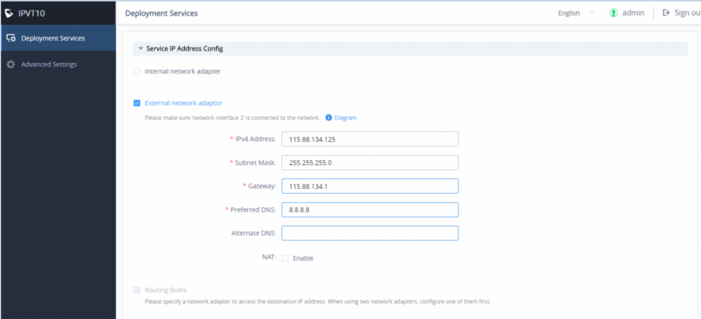
- Scenario 2: The server is deployed on the external network. The end-users use the service via the public network. Users need to configure the external IP address.
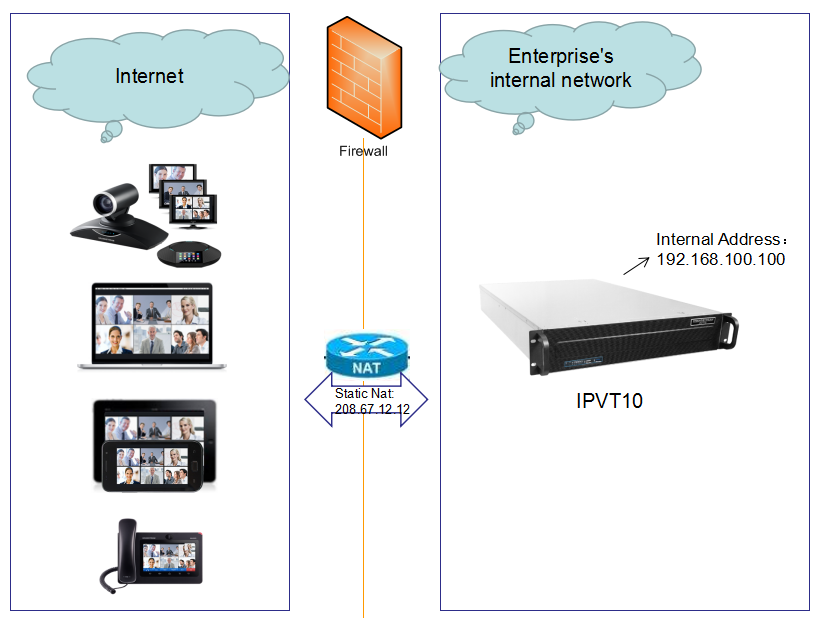
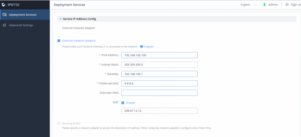
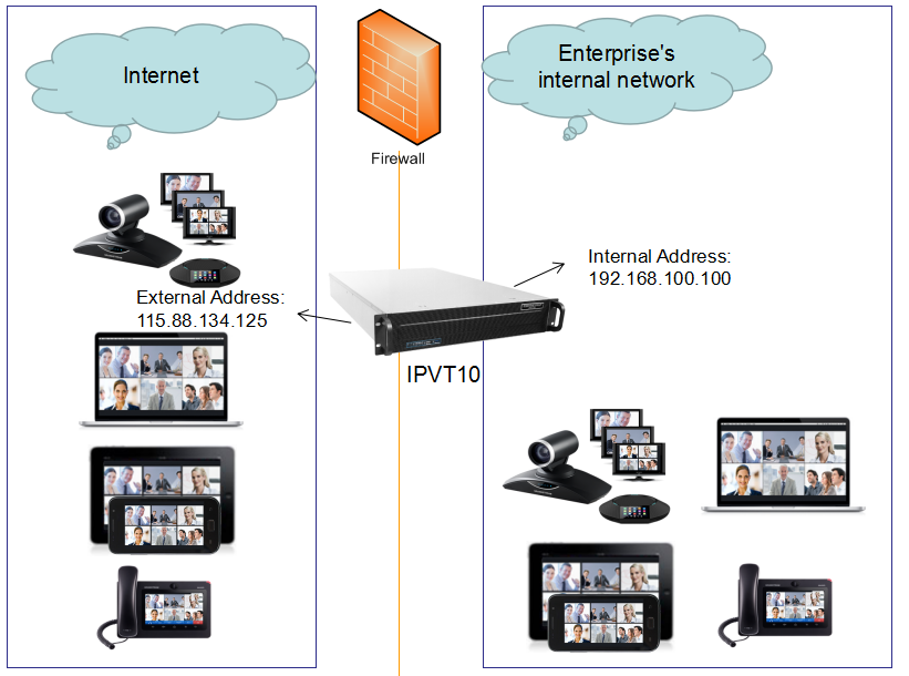
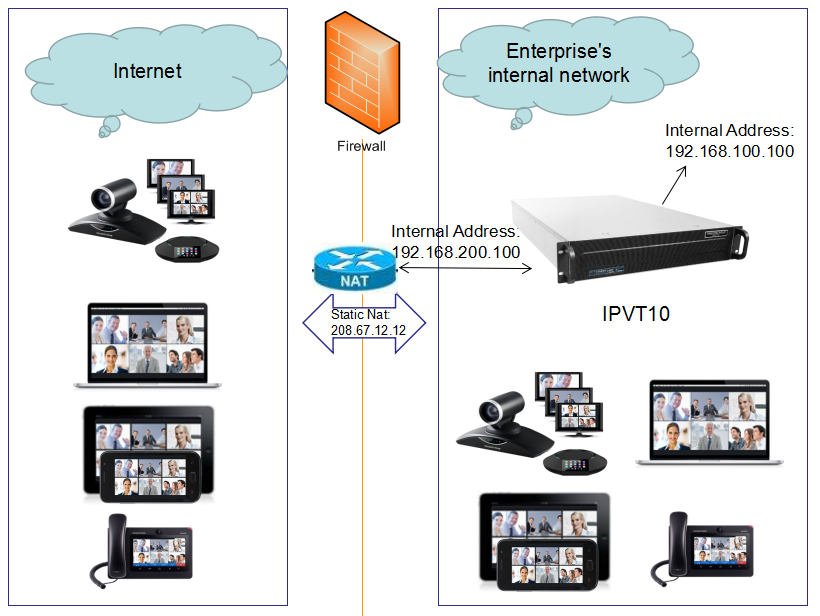
- Scenario 3: The server is deployed on the internal network. The end-users use the service via the public network. In this case, users need to configure the internal IP address and NAT in the server.
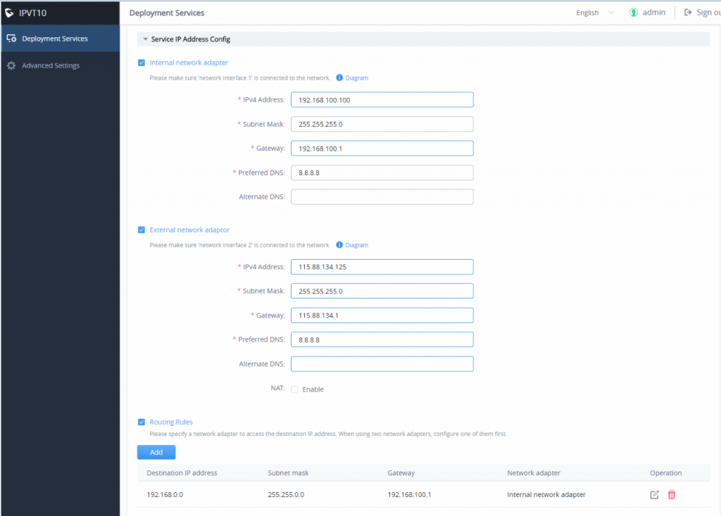
- Scenario 4: The server is deployed on the internal network. The end users can use the service via both internal and external networks. In this case, users need to configure the server with both internal network and external network and routing rules.
- Scenario 5: The server is deployed on the internal network. The end users can use the service via the internal network and limit certain external IP addresses to access the service. In this case, users need to configure the internal network, external network, NAT, and routing rules in the server.
Description | |
Native Domain Name | Configures the domain name of the IPVT10 server. |
Internal Network Adapter | Configures Internal Network Adapter’s parameters. |
External Network Adapter | Configures External Network Adapter’s parameters. |
IPv4 Address | Configures the IP Address for IPVideoTalk Portal. |
Subnet Mask | Configures the Subnet Mask. |
Gateway | Configures the default Gateway. |
Preferred DNS | Set the Preferred DNS. |
Alternative DNS | Set the Alternative DNS. |
NAT | Enable/Disable NAT. It allows users to set the IP address of NAT or the dynamic domain name of NAT. |
Routing Rules | Set the advanced configuration Routing Rules to ensure accessing the destination IP address when using two Network Adapters. |
Use Custom Certificate | Configures the key of the custom certificate. |
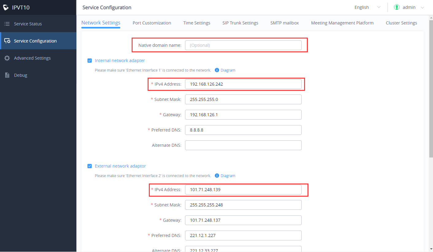
Please refer to the following steps:
- Login IPVT10 Web UI.
- Go to “Service Configuration” 🡪 “Network Settings”, as the figure is shown below:
3. (Optional) Users could configure the domain name of the IPVT10 server, and users have to own the permission of this domain name. Users also need to point this domain name to the IP address of the IPVT10 configured address.
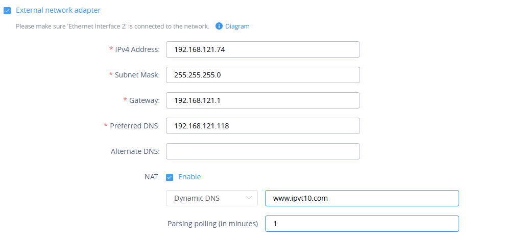
4. According to the actual requirements, users could configure the 1 or 2 network adapters. Users could configure Internal Network Adapter only, External Network Adapter, or both.
5. Users need to configure “IPv4 Address”, “Subnet Mask”, “Gateway”, “Preferred DNS”, and “Alternative DNS” (optional) for the network adapter.
6. (Optional) If the selected adapter is an external network adapter, users could configure static NAT or dynamic NAT for the IPVT10. If the user configures a dynamic domain name, the user needs to configure the interval (count by minutes) to resolve the IP address of the domain name. The default setting is 1 minute.
7. When two network adapters are configured, users must configure the routing rules based on the actual requirements by clicking the icon. Multiple routing rules can be configured in the IPVT10 server. Users can also edit and delete a certain routing rule.
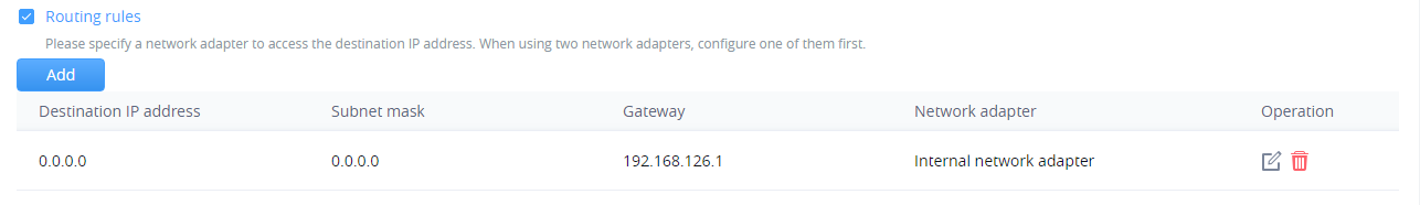
Parameters | Description |
Destination IP Address | This is used to configure the destination IP address for the network. This option must be configured with the Subnet Mask option. |
Subnet Mask | This is used to configure the subnet mask. |
Gateway | This is used to configure the gateway of the destination network. |
Network Adapter | This is used to select the server network adapter for the destination network. |
- (Optional) If users set the domain name as the in the IPVT10, users could also set “Use Custom Certificate” like the screenshot shown below:
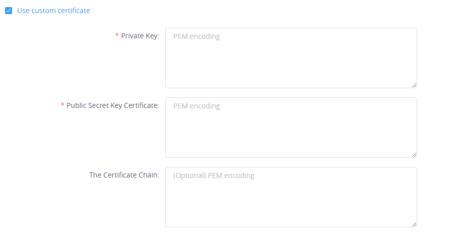
9. Continue to fill in the other configuration options. For the first deployment, users must fill in all required fields.
10. User could click to save the configuration and click on “Apply Now” to apply the entire configurations of this page to the server. When the deployment is complete, it will take effect immediately.
Configure Service NAT Interfaces
To use the IPVT10 service on the enterprise’s private network, users could customize the service port. The default service ports are shown below:
Server Components | Protocol | Default Port | Descriptions |
Web Server | HTTP | 80 | Conference Web UI, Requests Management, API Server Note: the Nginx web server has been updated to version 1.22.1 on firmware release 1.0.6.14
|
Web Server | HTTPS/WSS | 443 | Conference Web UI, Requests Management, API Server, Connect to Web socket |
SIP Server | TCP/UDP | 5060 | SIP signaling access for different devices, Trunk/PSTN Connection |
SIP Server | TLS | 5061 | SIP signaling access for different devices, Trunk/PSTN Connection |
SIP Server | UDP | 1719 | H323 RAS Registered Access |
SIP Server | TCP | 1720 | H323 Q93 Call Access |
Media Server | TCP/UDP | 5062 | External control port |
Media Server | UDP | 60000-65000 | Port range of media streams: Requirements: Port starting should not be lower than 1024, the range is not less than 3000. |
Please refer to the following steps:
- Login IPVT10 Web Management UI.
- Click on the “Service Configuration” on the left side of the UI and select “Service Port Configuration”, as shown below:
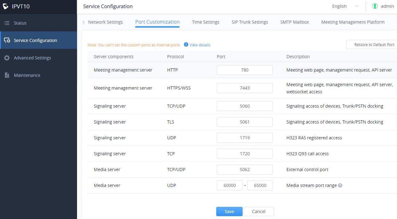
3. Click to open the menu “Service Port Configuration” to customize the service ports based on the requirements.
4. When finished updating the ports, click on the “Save” button to save the configuration, and click on the button “Apply Now” to confirm the customized service ports. The server will reboot to apply the changes.
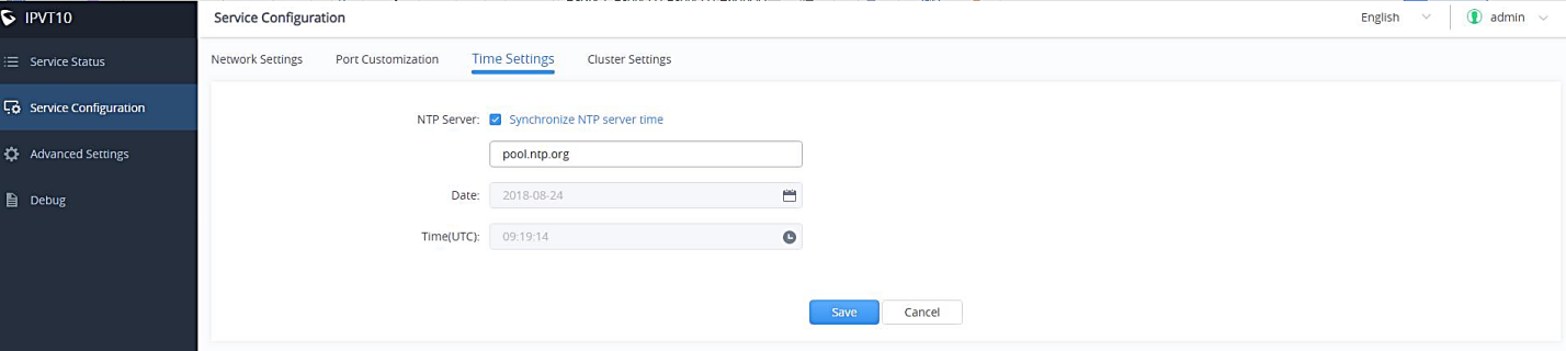
Time Configuration
Users could check the current time and time-zone of the server and correct it at any time to avoid the meeting time inaccurate or cannot be launched issues.
Please, refer to the following steps:
- Login IPVT10 Web UI.
- Click on “Service Configuration”, and configure the “Time Settings” options, as the figure is shown below:
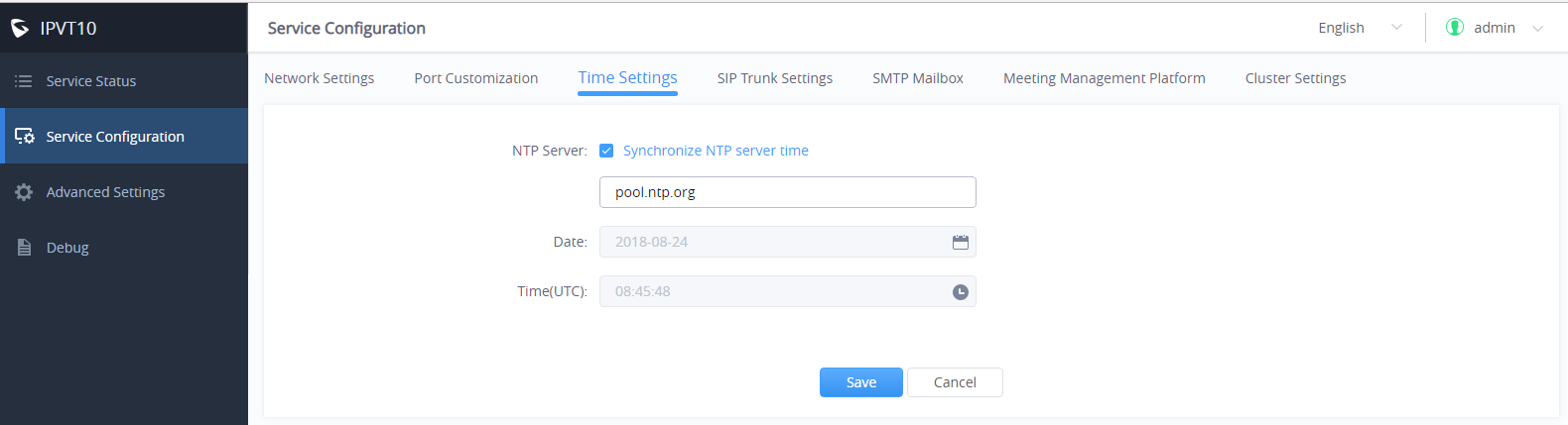
3. It shows the current time of the server by default.
4. Users could set whether to synchronize the SNTP server time. If there is no available SNTP server, users could adjust the date and time manually.
5. Users could click on “Save” to update the server time immediately.
Configure SIP Trunk Service Address
(Optional) Users could configure the SIP Trunk server address based on the actual requirements. If users configure this service, users could use the PBX platform or PSTN Trunk server to connect via IPVideoTalk conference system, user also cloud set DialPlan to dial out the 3rd party PBX platform.
- Connecting to the IPVideoTalk Conference System with 3rd Party Platform (PBX or PSTN)
To connect the IPVideoTalk Conference System with a 3rd party platform, please refer to the following steps:
- Login IPVT10 Web Management UI.
- Go to “Service Configuration🡪SIP Trunk Settings”, and users will see the page below:
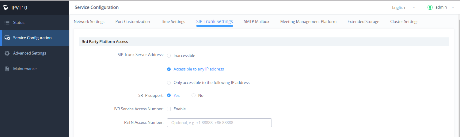
3. Configure the SIP Trunk server address. If the option “Accessible to any IP address” is checked, all the IP addresses can connect to the IPVT10 server. If the option “Only accessible to the following IP address” is checked, users need to input the certain IP addresses which can access the IPVT10 server. Users could configure up to 10 IP addresses, and only the candidates can access the IPVT10 conference system.
4. Check and choose whether 3rd party supports SRTP. If supported, then use SRTP otherwise use RTP instead.
5. (Optional) Configure the IVR voice access number. If the configured Trunk server connects to the conference via IVR voice access number, users need to configure the IVR voice access number before using the service. If the Trunk server supports recognizing the IPVideoTalk conference ID, and dials to the IPVT10 server via the conference ID, then users do not need to configure the IVR voice access number.
6. (Optional) Configure the PSTN access number, this is only used for display. If users want to show the PSTN access number in the conference invitation Emails, or the meeting details, users could configure this option. If there are multiple PSTN access numbers, please separate the numbers by comma (e.g. +861234567, +8687654321).
Typical Scenarios
Scenario 1
There are one or more SIP Trunk servers in the enterprise, and the administrator wants the users to dial the meeting by IPVT10 meeting ID directly.
Prerequisites:
SIP Trunk server needs to be able to recognize the conference ID of IPVT10. When users dial this conference ID, users will be connected to the IPVT10 server.
Configuration:
Users need to configure one or more SIP Trunk server addresses.
Scenario 2
There are one or more SIP Trunk servers in the enterprise, and the administrator wants the users to dial the unique access number and follows the IVR to input the conference ID to join the meeting.
Prerequisites:
SIP Trunk server needs to be able to recognize the IVR access number. When users dial this IVR access number, users will be connected to the IPVT10 server.
Configuration:
- One or more SIP Trunk server addresses
- IVR voice access number
Scenario 3
There are one or more PSTN Trunk servers in the enterprise, and the administrator wants the PSTN users to access the IPVT10 conference.
Prerequisites:
Users need to configure the unique accessible PSTN numbers for the PSTN Trunk servers. When users dial the PSTN numbers, users can connect to the IPVT10 server.
Configuration:
- One or more SIP Trunk server addresses
- (Optional) IVR voice access number
- If users want to show the PSTN access number in the invitation Emails, users could configure the PSTN access number option.
Scenario 4
There is one SIP Trunk server and one PSTN Trunk server in the enterprise, and the administrator wants the PSTN users and SIP users both could join in the IPVT10 conference.
Prerequisites:
- If users connect to the SIP Trunk server via IVR, the IVR access number should be recognized (refer to scenario 2). Otherwise, please kindly refer to scenario 1.
- Users need to configure the unique accessible PSTN numbers for the PSTN Trunk servers. When users dial the PSTN numbers, users can connect to the IPVT10 server.
Configuration:
- One or more SIP Trunk server addresses
- (Optional) IVR voice access number
- If users want to show the PSTN access number in the invitation Emails, users could configure the PSTN access number option.
- Dial out to the Accounts on the 3rd Party Platform
If users need to join the IPVT conference with the 3rd party platform accounts, users need to configure the 3rd party platform accounts rules and server address in the IPVT10. Please, refer to the following steps:
- Login IPVT10 Web Management UI.
- Click on the “Service Configuration” on the left side of the UI, and check the figure below:
- Users could select using which IP address of the IPVT10 server (internal network/external network) to call the third-party platform.
- Input the dialing prefix, and it is used to recognize the accounts in the 3rd party platform. The special characters (e.g. + * #) are necessary. For example, the account in the 3rd party platform is +86 88888, and the +86 is the dialing prefix. The call will be made to the target server including the prefix.
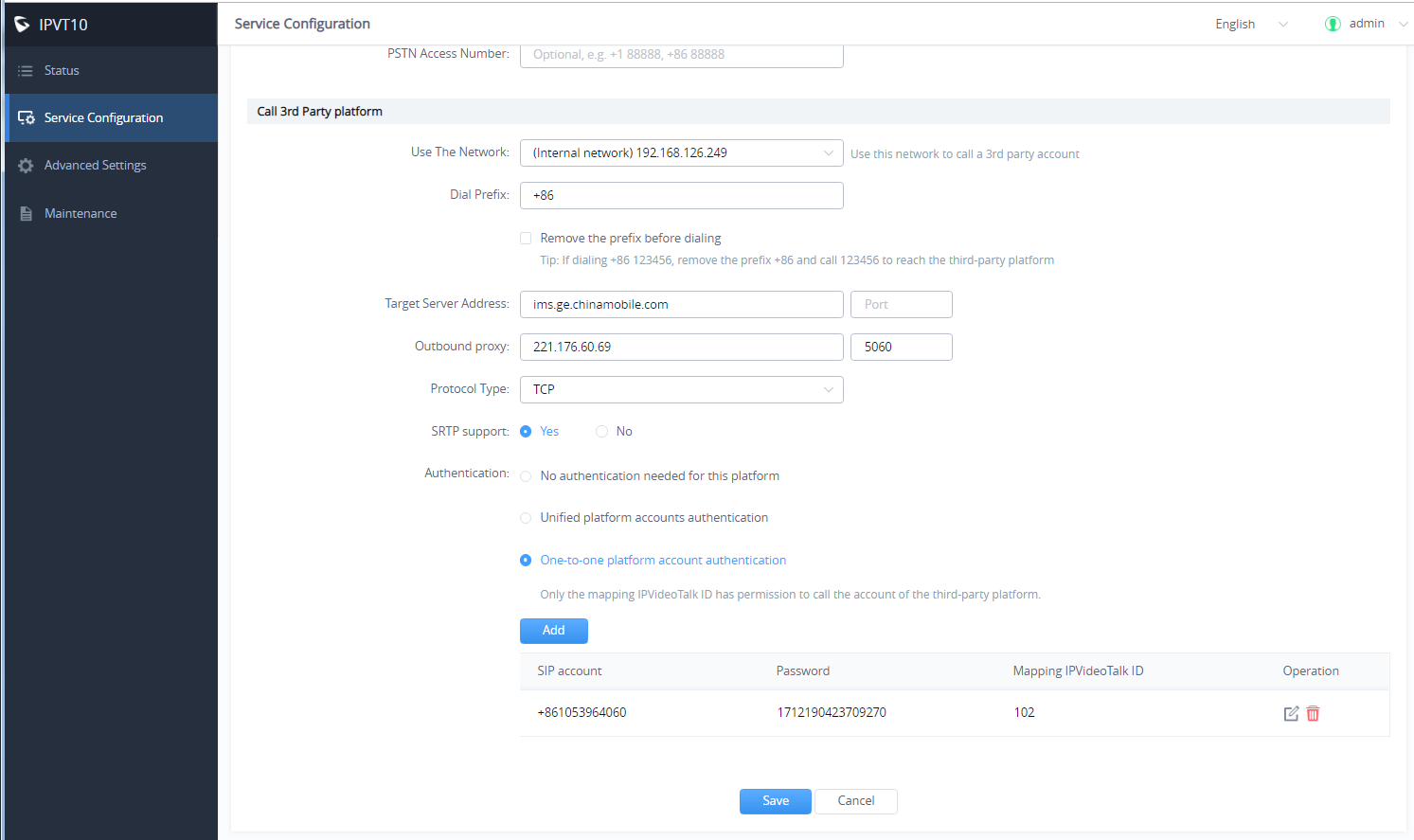
5. Configure the server address and port for the target server, which is the server IP address or domain name of the 3rd party platform, and the port number of the target server.
6. Select the “Protocol Type” for the 3rd party platform (TCP/TLS/UDP).
7. Check and choose whether 3rd party supports SRTP. If support, then use SRTP otherwise use RTP instead.
- Unified platform accounts authentication: Users only need to configure 1 SIP account and password on the 3rd party platform, the IPVT10 will always use this SIP account and password authentication to access the 3rd party platform.
- One-to-one platform account authentication: Users need to configure multiple SIP accounts, passwords, and mapped IPVT ID on the 3rd party platform. Only the authenticated IPVT IDs can access the 3rd party platform. Users could add multiple accounts or edit/delete the accounts.
8. When the configurations are done, users click to save the configuration and click on the “Deploy to server” button to apply the changes. The server will reboot to apply the changes.
Configure SMTP Mailbox
This Email box is used to send the meeting invitation Emails, meeting reminders, and other notifications as the Email sender. If users do not configure this Email box, the system cannot send Emails to inform the meeting participants.
Please, refer to the following steps:
- Login IPVT10 Web UI.
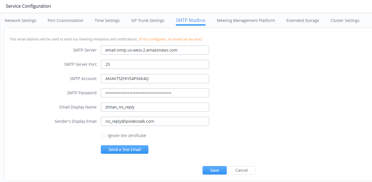
- Click on “Service Configuration” and configure the “SMTP Mailbox” options, as shown below:

3. Input the mailbox and configure the options below:
Parameters | Example |
SMTP Server | smtp.gmail.com |
SMTP Port | 465 |
SMTP Username | test@gmail.com |
SMTP Password | *** |
Mailbox Display Name | User’s enterprise name |
4. If the SMTP server is a self-signed certificate, you need to check “Ignore certificate“. Otherwise, the SMTP mailbox cannot send mail.
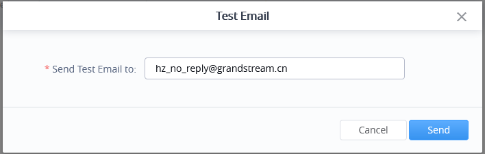
5. Before saving the SMTP mailbox configuration, users could click on the “Send a Test Email” button, and input the test email address in the pop-out window to receive the test email, then click on the “Send” button to send out the test email. Then, users could go to the test email box to check the test email. If the user could receive the test email, the SMTP mailbox has been configured correctly. Otherwise, the user needs to check the SMTP mailbox configuration on the Web UI.

6. Users could click to save the configuration and click on “Apply Now” to apply the entire configurations of this page to the server. When the deployment is complete, it will take effect immediately.
Configuring Conference Management Platform Information
The Conference Management Platform provides the following features:
- Instant Meeting: Create a temporary meeting for a certain conference client.
- Schedule Meeting: Remote schedule a meeting for a certain conference client.
- Join Meeting: Join a meeting with the browser WebRTC client.
- Manage Meeting: Start/Cancel scheduled meetings, check the meeting histories, check the meeting participants list after the meeting, and other statics information.
- Manage Recording Files: Check/Download cloud recording files.
- Manage Clients: Manage all clients which are connected to the IPVT10 server, such as GVC32XX.
- Add User: Create user accounts for the Conference Management Platform.
Please, refer to the following steps:
- Login IPVT10 Web UI.
- Click on “Service Configuration”, and configure the “Meeting Management Platform” options, as the figure is shown below:
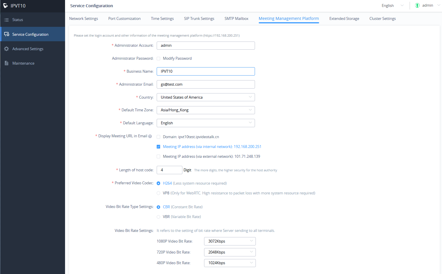
3. Input the parameters as follows:
Parameters | Description | Example |
Admin Username | Conference Management Platform administrator’s username. | The default value is “admin”. |
Admin Password | Conference Management Platform administrator’s password. | The default value is “admin”. |
Enterprise Name | Conference Management Platform enterprise display name | User’s enterprise name |
Admin Email | This is used to retrieve the passwords or receive system notification Emails. | Administrator’s Email box |
Country | Enterprise Location | The default value is “US”. |
Language | Conference Management Platform language | The default value is “English”. Note: If the language changes to Spanish or Russian, the conference IVR will also be switched to Spanish or Russian. While for all other languages the IVR will still be English. |
Displaying Meeting Address in Email | Select the meeting address that needs to be released in public, which is the meeting address displayed in the invitation email. Users could select the domain name, internal IP address, and external IP address which has been configured in the server. | If the domain name could be resolved automatically to the internal IP address or external IP address according to the local network, users only need to release the domain name in public. |
Length of Host Code | Set the host code length of the meeting. Supports [4 – 32] digits. Note: The host code is used to obtain the permission of the host in the meeting. | The default setting is 4 digits. If the user needs to improve the security, he can increase it up to 32 digits. |
Force to use MCU Mode | The default setting is Disabled | |
Force to send 1080p video to 3rd-party Endpoint | The default setting is Disabled | |
Video Bit Rate Type Settings | Select the type of video bitrate for the media server, dynamic bit rate, or static bit rate. | The default setting is the static bit rate. |
Video Bit Rate Settings | Select the video bit rate sent to each client by the media server, including the bit rate corresponding to various resolutions. | The default setting is the maximum supported performance of the server, which is based on the local network conditions. |
4. Click on “Apply Now” to apply the entire configurations of this page to the server. When the deployment is complete, it will take effect immediately.
Third-Party Speech Recognition Service Configuration
Users can configure the Speech Recognition Service in their Google account for IPVT10 to benefit from Google Speech Recognition Services to convert meeting speech to text as meeting records.
Prerequisite: The user needs to have a Google account that has speech-to-text service enabled, and the user needs to download the relevant certificates. (Users may need to check Google’s official website to learn more details about this service.)
- Login IPVT10 Web UI.
- Click on “Service Configuration”, and configure the “Meeting Management Platform” options, as the figure is shown below:

3. Check the “Enable” option and upload the service certificate of Google Speech Recognition.
4. Click the “Save” button to apply the changes, the Google Speech Recognition service will be enabled during the meeting (WebRTC client). The meeting speech will be converted to live meeting captioning during the meeting.
Extended Disk
If the user needs more storage disks or prefers to store meeting files on other extended disks, the user could follow the steps below to set up the extended disks:
- Login IPVT10 Web UI.
- Go to “Service configuration” and configure “Extended Storage” options.
- Select to activate or inactivate “NFS Storage Disk”, as the figure shows below:

4. Fill in the following information as required:
Parameters | Description | Example |
NFS Extended Disk IP Address | Fill in the IP address of the NFS extended disk. This IP address must be reachable for the IPVT10 server. Otherwise, the setup will be failed. | |
Storage Address | Fill in the file path which will be stored in the NFS extended disk, and the root directory is required. | e.g. /folder1/folder2 |
NFS Version | The currently installed system version of NFS is V3 or V4, users need to select the actual version of NFS. Otherwise, the negotiation between IPVT10 and NFS will be failed. |
5. Click on “Apply Now” to apply the entire configurations of this page to the server. When the deployment is complete, it will take effect immediately.
Cluster Settings
If users need multiple IPVT10 servers to create a cluster, users need to set one IPVT10 server as the cluster host server. Please, refer to the following steps:
- Login IPVT10 Web UI.
- Go to “Service configuration” and configure “Cluster Settings” options。
- Select to check the option “Active cluster service” to activate the server cluster service, and use the IPVT10 as the cluster host server, as the figure is shown below:
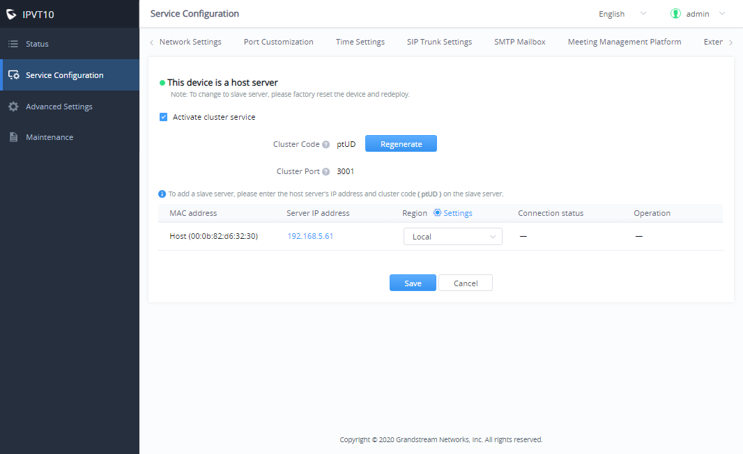
- Users need to click to save the configuration and click on “Apply Now” to set up the cluster host server. Then, the cluster host server IPVT10 will be activated.
- In the slave servers, users need to input the “Cluster Code” (e.g. “Cv1R” in the screenshot above, case sensitive). Then, the connection between the cluster host server and the slave server will be established.
Slave Server Management
Users could log in IPVT10 cluster host server to check the information of slave servers in the cluster, and block/delete the slave servers on the cluster host server IPVT10’s Web UI.
Please, refer to the following steps:
- Login IPVT10 Web UI.
- Go to “Service configuration” 🡪 “Cluster Settings”, and users could check the information of the slave servers.
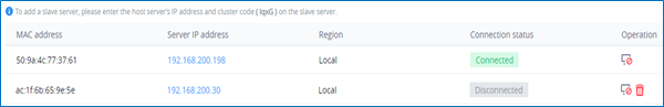
3. Users could click on the IP address of the slave server, and log in to the Web UI of the slave server with the credentials.
4. Users could click on the icon ![]() to block the connection of the slave server. When the connection is blocked, the slave server IPVT10 cannot establish the connection with the cluster host server, and the cluster host server IPVT10 cannot negotiate with this slave server. Users could also click on icons to cancel blocking and recover the connection between the slave server and the host server.
to block the connection of the slave server. When the connection is blocked, the slave server IPVT10 cannot establish the connection with the cluster host server, and the cluster host server IPVT10 cannot negotiate with this slave server. Users could also click on icons to cancel blocking and recover the connection between the slave server and the host server.
5. If the connection between the slave server and the host server is lost, or the slave server is not available anymore, users could click on the icon ![]() to delete the slave server.
to delete the slave server.
6. Users need to click on the “Save” button to save the configuration and click on “Apply Now” to take effect on the device.
Configure IPVT10 Server Region
Users could manage the clustered IPVT10 servers in different regions. For example, if IPVT10 servers A, B, and C are assigned to region 1, and IPVT10 servers D, and E are assigned to region 2, the GVC devices or IPVideoTalk IDs which are assigned to region 1 can only use the resources in the IPVT10 servers which belong to region 1, and they cannot access to use the resources in region 2.
- Login IPVT10 Web UI.
- Go to “Service configuration” 🡪 “Cluster Settings”, and users could view the Host/Slave Servers List.
- Users could change the region of the IPVT10 server under the “Region” menu by clicking the drop-down menu. The default setting is “Local”. If users want to add a new region, please click on the “Settings” icon beside the “Region” menu option, as the following figure shows.
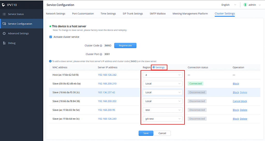
4. Users need to click on the “Save” button to save the configuration and click on “Apply Now” to take effect on the device.
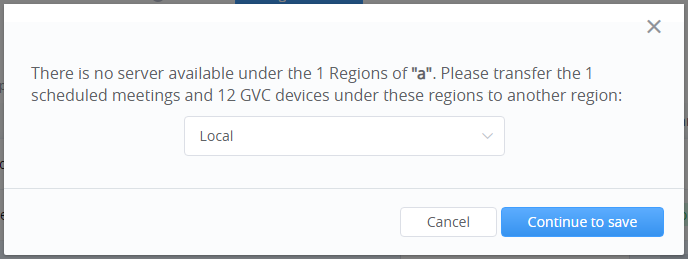
Note: If there is a region that does not include any IPVT10 server, all the scheduled meetings in this region cannot be started, and there will be a prompt to indicate to the user that all scheduled meetings in this region will be moved to another region. As shown in the following figure:
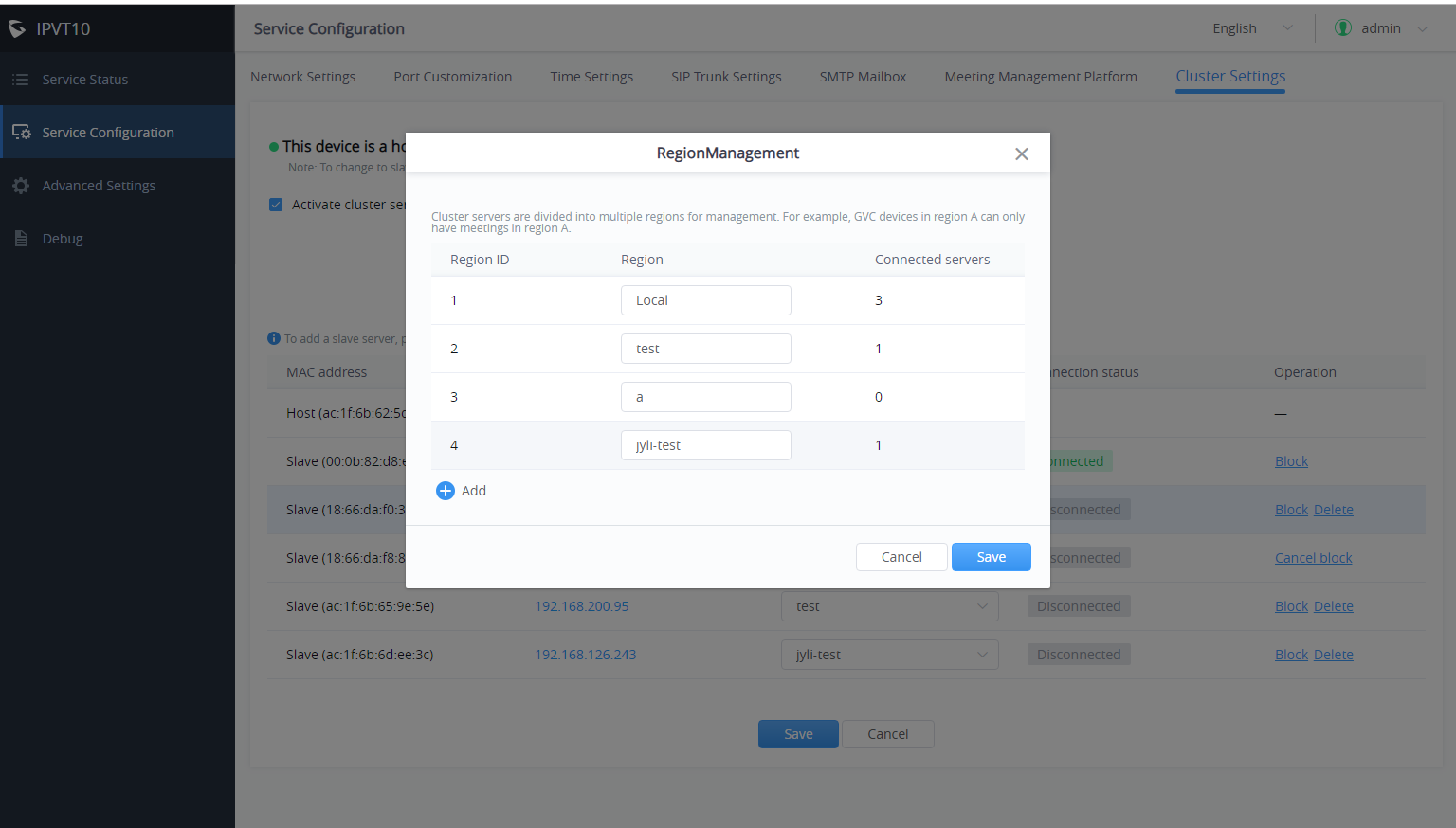
Region Management
Users could add multiple new regions and change the names of the regions.
- Login IPVT10 Web UI.
-
Go to “Service configuration” 🡪 “Cluster Settings”, and click the icon
 besides the Host/Slave Servers List, users could see the prompt as the figure shows below:
Cluster Code
Users could generate a new cluster code in the cluster, and all slave servers cannot connect with the cluster host server without the new cluster code.
Please, refer to the following steps:
- Login IPVT10 Web UI.
- Go to “Service configuration” 🡪 “Cluster Settings” and click on the button
 to generate a new cluster code for the cluster service.
 - Users need to click on the “Save” button to save the configuration and click on “Apply Now” to affect the device.
Then, all slave servers cannot connect with the cluster host server without the new cluster code. Users need to input the cluster code again in the slave servers to recover the connection with the cluster host server.
Configure Slave Server
Network Settings
Options Descriptions
Parameters | Description |
Network Adapter | Configures Network Adapter’s parameters, which requires establishing the connection with the host server. |
IPv4 Address | Configures the IP Address for IPVideoTalk Portal. |
Subnet Mask | Configures the Subnet Mask. |
Gateway | Configures the default Gateway. |
Preferred DNS | Set the Preferred DNS. |
Alternative DNS | Set the Alternative DNS. |
NAT | Enable/Disable NAT and set the NAT IP address. |
Please, refer to the following steps:
- Login IPVT10 Web UI.
- Go to “Service configuration” 🡪 and “Network Settings”, as the figure is shown below:
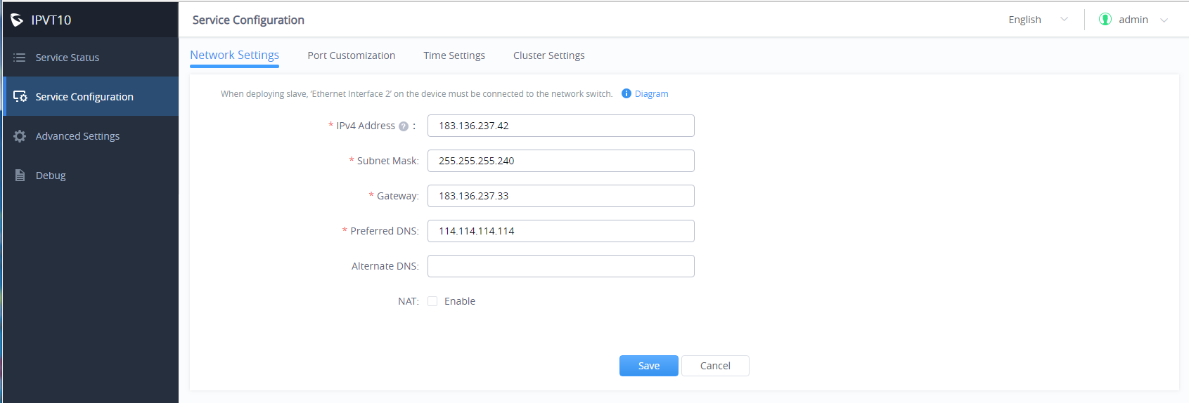
3. Users need to configure “IPv4 Address”, “Subnet Mask”, “Gateway”, “Preferred DNS”, and “Alternative DNS” (optional) for the network adapter.
4. (Optional) If the selected adapter is an external network adapter, users could configure static NAT for the IPVT10.
Continue to fill in the other configuration options. For the first deployment, users must fill in all required fields.
Users need to click to save the configuration and click on “Apply Now” to apply the entire configurations of this page to the server. When the deployment is complete, it will take effect immediately.
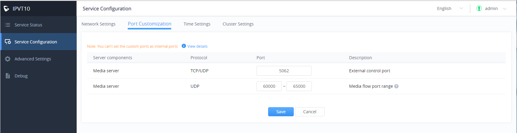
Configure Service NAT Interfaces
(Optional) users could customize the service port. Our default service ports are shown as following below:
Server Components | Protocol | Default Port | Descriptions |
Media Server | TCP/UDP | 5062 | External control port |
Media Server | UDP | 60000-65000 | Port range of media streams: Requirements: Port starting should not be lower than 1024, the range is not less than 3000. |
Please, refer to the following steps:
- Login IPVT10 Web Management UI.
- Click on the “Service Configuration” on the left side of the UI and select “Port Customization”, users will see the page below:
3. Users could customize the service ports based on the requirements.
4. When users finish updating the ports, users need to click to save the configuration and click on the button “Deploy Now” to confirm the customized service ports. The server will reboot to apply the changes.
Time Configuration
Users could check the current time and time-zone of the server and correct it at any time to avoid the meeting time inaccurate or cannot be launched issues.
Please, refer to the following steps:
- Login IPVT10 Web UI.
- Click on “Service Configuration”, and configure the “Time Settings” options, as the figure is shown below:
3. It will show the current time of the server by default.
4. Users could set whether to synchronize the SNTP server time. If there is no available SNTP server, users could adjust the date and time manually.
5. Users need to click to save the configuration and click on “Apply Now” to update the server time immediately.
Cluster Settings
Users need to input the IP address of the cluster host server and the cluster code in the slave server to finish the configuration.
Please, refer to the following steps:
- Login IPVT10 Web UI.
- Click on “Service Configuration” 🡪 “Cluster Settings”, as the figure is shown below:
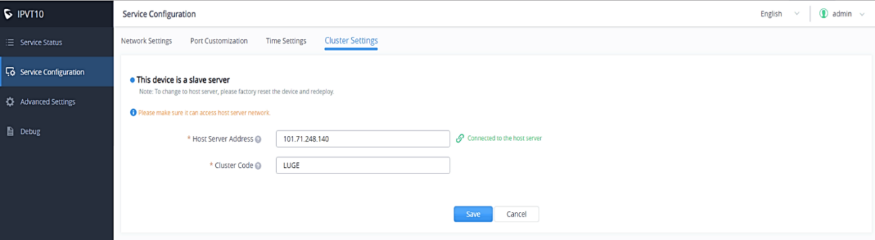
3. Input the IP address of the cluster host server. This IP address must be a reachable address for the slave server.
4. Input the Cluster Code in the slave server (case sensitive).
5. Users need to click to save the configuration and click on “Apply Now” to update the server time immediately.
Advanced Settings
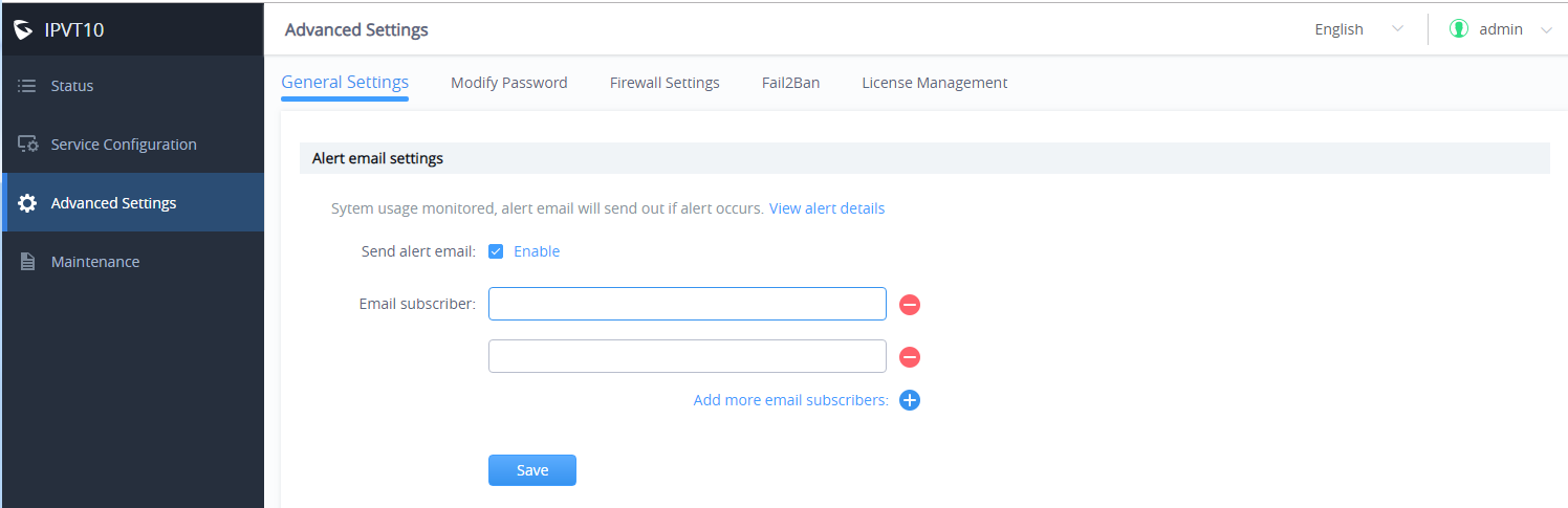
Alarm Email Setup
Users can configure and enable Alarm Email. The alarm email includes high CPU usage, HDD abnormal, slave machine connection abnormal, system reboot, system upgrade, admin login failed continuously, password changed, etc.
- Login IPVT10 Web UI.
- Click on “Advanced Settings” and go to “General Settings”.
- Click to enable “Send Alarm Email” and input the receiver email addresses, multiple email addresses are allowed.
- Click “Save” to save the setting. Alarm Emails would be sent to the subscriber’s email addresses once alarm events happened
Enable/Disable SSH
If your IPVT10 server encounters any failure, you may need to contact Grandstream technical support to troubleshoot the problem. You can enable SSH service on the IPVT10 server’s Web UI, to allow our technical support to access the IPVT10 server remotely for troubleshooting purposes.
Please refer to the following steps:
- Login IPVT10 Web UI.
- Click on “Advanced Settings” and go to “General Settings”.
- The default SSH port is 26222, and users could change the SSH port by editing the port number directly.
- Click on “Enable SSH”.
- If users want to disable the SSH service, please click on the button “Disable SSH”.
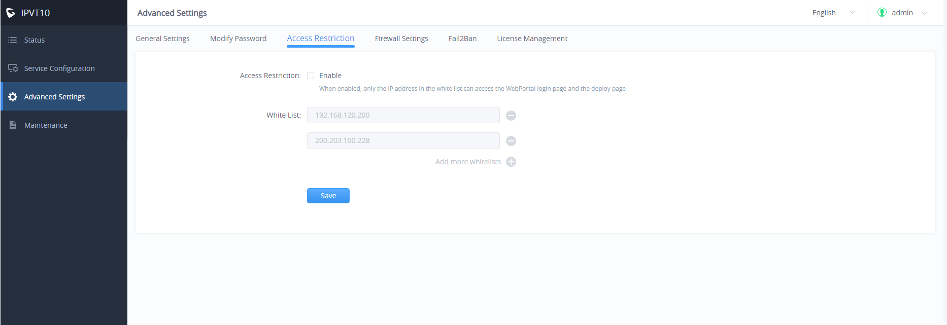
Access Restrictions
Users can set a white list to only allow specific IP addresses to access the deployment management page and the meeting management platform. Please refer to the following steps to enable this feature.:
- Login IPVT10 Web UI.
- Click on “Advanced Settings” and go to “Access Restriction”.
- Enable this option.
- Then, enter multiple IP addresses and IP segments on the white list, such as 192.168.1.1/24. This is a mandatory option.
- Click the “Save” button to complete the setup.
Firewall Settings
Firewall configuration is provided to protect the device and system from malicious attacks by processing different data passing through the system properly and ensuring bandwidth and security.
In “Advanced Settings”, go to “Firewall” web GUI, user can see the Firewall Config page to set up and adjust the related parameters accordingly.
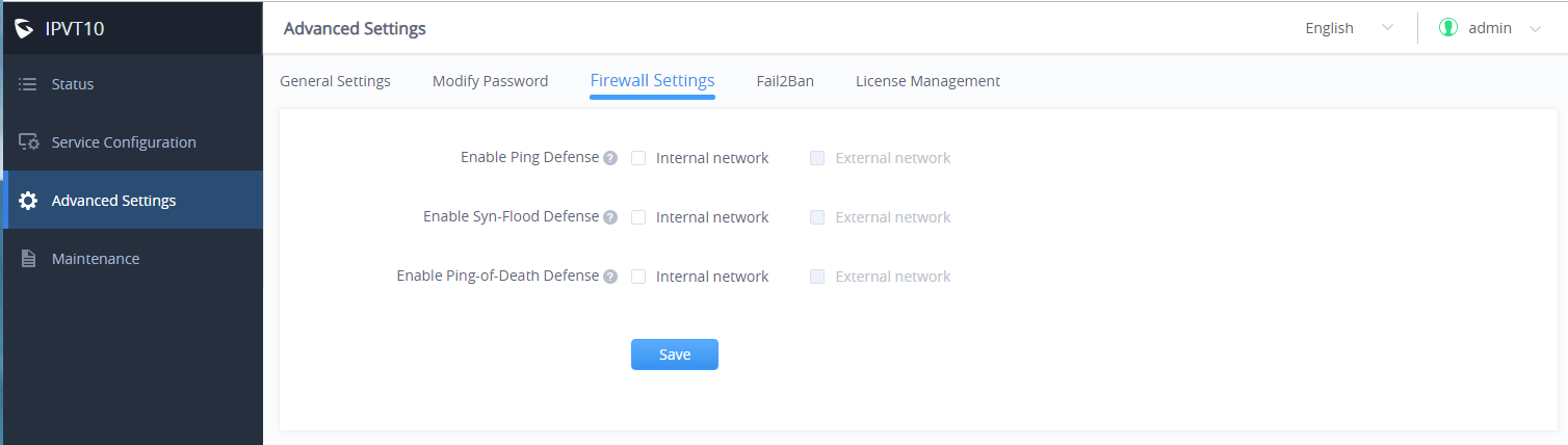
Parameters | Description |
Enable Ping Defense | If enabled, no echo response to the “PING” ICMP message. Default disabled. |
Enable Syn-Flood Defense | Enable to protect of the device from flood attacks or DDoS attacks. Default disabled. |
Enable Ping-Of-Death Defense | Enabled to protect the device from Ping of Death (PoD) flood DDoS attack. Default disabled. |
Fail2Ban
Fail2Ban feature will discover and block authentication errors that occur during SIP registration, authentication, and access connections. If a host fails and exceeds the maximum allowed value (named as the matching threshold) within the specified time, IPVT10 will mark out and block the host for a period. This feature helps to detect and prevent violent attacks on the IPVT conferencing system in a timely manner.
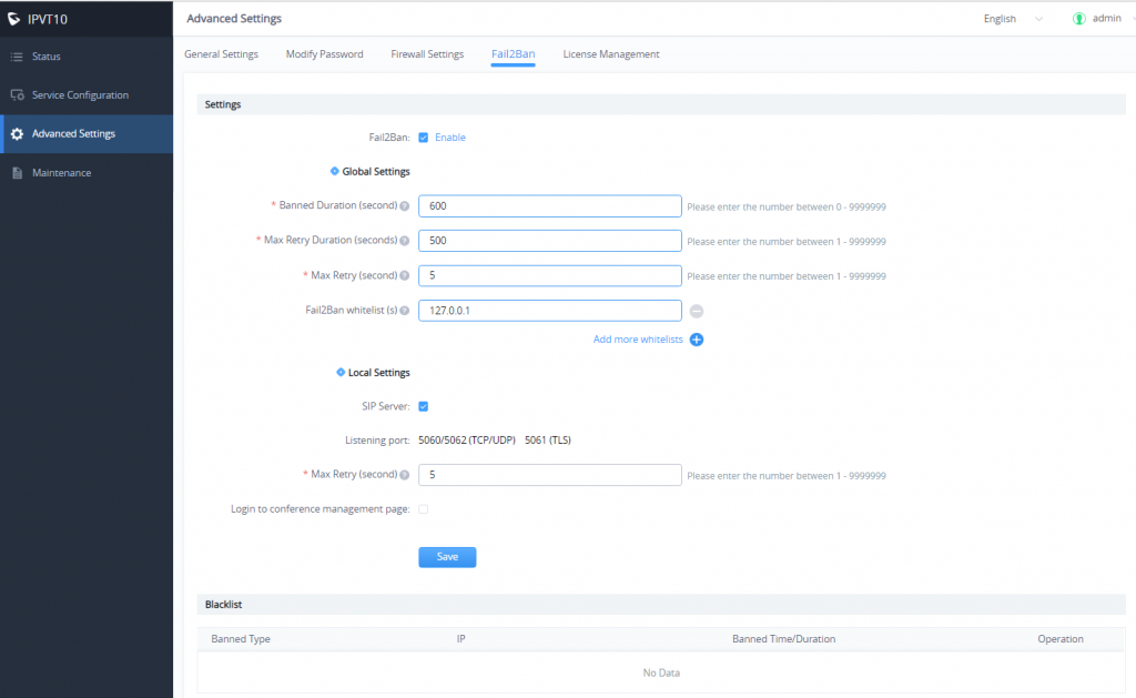
Parameters | Description |
Settings | |
Enable | Click to enable Fail2Ban. Default settings are disabled. If enabled, it will be effective for SIP Server and the login to the Conference Management Platform. |
Global Settings | |
Banned Duration (seconds) | Configure host forbidden timespan by the firewall, in seconds. Default value 300 seconds (5 minutes). the host will be always banned. |
Max Retry Duration (seconds) | Within this duration (in seconds), if a host exceeds the max times of retry as defined in “Max Retry”, the host will be banned. The default setting is 600. |
Max retry | Configure the number of authentication failures during “Max Retry Duration” before the host is banned. The default setting is 5. |
Fail2Ban Whitelist | Set the Whitelist via IP address or a DNS domain name. Fail2Ban will not block hosts in the Whitelist. A maximum of 20 hosts are allowed in the Whitelist. |
Local Settings | |
SIP Server | Enable to set up an individual matching threshold for the “SIP Server”. Default is disabled. Note: Listening Port is Not configurable. Current supported ports: 780 (HTTP) 7443 (HTTPS/WSS) |
Login to conference management page | Allows login to the Conference management page. Default is disabled. Note: Listening Port is Not configurable. Currently supported ports: 5060/5062 (TCP/UDP) and 5061 (TLS) |
Max retry | When the number of failed login attempts from an IP address exceeds the Max retry number, that IP address will be banned from accessing the Web GUI. |
Settings | |
Blacklist | Users will be able to view the IPs that have been blocked by IPVT10. |
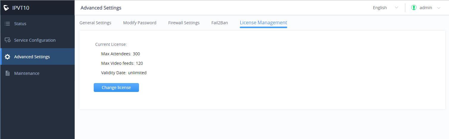
License Management
View License Information
Users could view the license information of the IPVT10 on its Web UI.
Please refer to the following steps:
- Login IPVT10 Web UI.
- Click on “Advanced Settings”, and go to “License Management”, users could check the current license information details as the screenshot shows below:
Update License
Users could update the license of the IPVT10 server on its Web UI.
Please refer to the following steps:
- Login IPVT10 Web UI.
- Click on “Advanced Settings” and go to the “License management” menu.
- Click on the “Change License” option.
- Upload the new license file into the IPVT10 server.
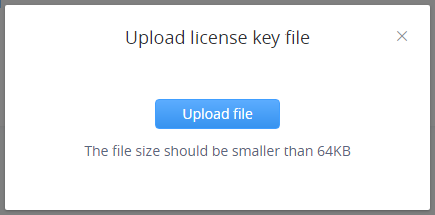
5. When finish uploading, users need to click on “Active Now” to apply for the new license on the IPVT10 server.
Maintenance
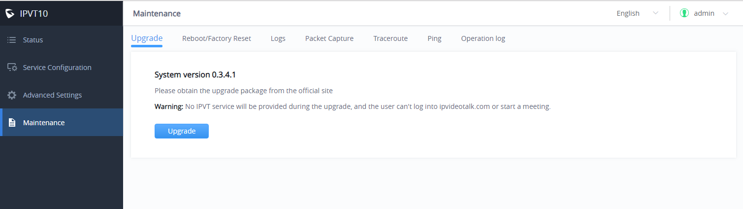
Upgrade
Users need to take into consideration the following notes when upgrading IPVT10:
- During the upgrading service, the IPVT10 service will be suspended, and users cannot log in to the Conference Management Platform or start meetings.
- It is suggested to upgrade the device when there are no scheduled or activated meetings during the period.
- It is suggested to download the upgrading firmware from Grandstream’s official website or use the firmware from Grandstream’s designated technical support.
Please refer to the following steps:
- Login IPVT10 Web UI.
- Click on “Maintenance”🡪 “Upgrade”.
- Click on “Upgrade”.
4. Select the upgrading firmware from the local PC and upload the firmware to the device.
5. When users click to confirm upgrading, the device will process upgrading the firmware. This process may take several minutes.
6. When the upgrading is complete, the server will restart the service automatically.
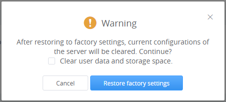
Factory Reset
When users restore the device to factory reset, all the data in the database server will be erased, including the meetings data and user’s data, as all the configurations in the server will be erased, and restored to the factory default configuration.
Please, refer to the following steps:
- Login IPVT10 Web UI.
- Click on “Maintenance“ 🡪 “Reboot/Factory Reset”.
- Click on “Factory Reset”.
- The system will pop up a prompt to ask the users to confirm “Are you sure to factory reset the device?”, and users could click on “Yes” to start to factory reset the device. All the data will be erased, and the service will be restarted. Users could also select to clear all user data or remain the data.
- If users only clear the configurations in the IPVT10, and remain the user’s data, all of the settings will be recovered to default settings, and all of the logcat will be deleted, the user’s data such as account information, scheduled meetings, meeting histories, and recording files will remain.
- If the user selects to clear all user data, all the configurations and user data will be erased from the IPVT10 server.
Reboot
Users could reboot the IPVT10 server on its Web UI. Please refer to the following steps:
- Login IPVT10 Web UI.
- Click on “Maintenance “🡪 “Reboot/Factory Reset”.
- Click on “Reboot” to reboot the IPVT10 server, and the current meetings which are in progress will be terminated.
System Logs
Users could check and download the logs of each component from the IPVT10 server (e.g. MCU/SIP server/WebRTC/Conference Management Platform).
Please refer to the following steps:
- Login IPVT10 Web UI.
- Click on the “Maintenance” 🡪 “Logs” menu, as the figure shows below:
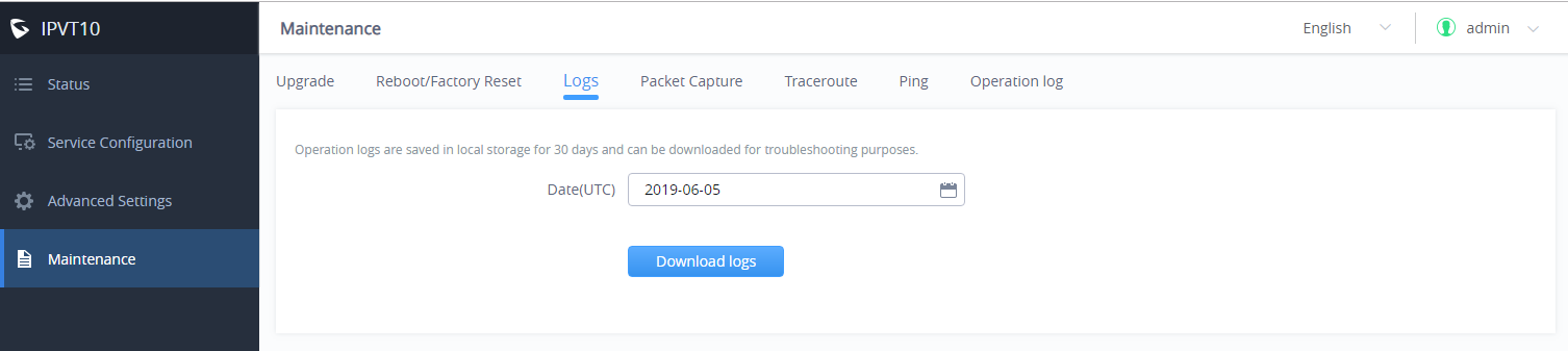
3. Select the date of generating the logs. Users could select the date up to the past 30 days.
4. Click on “Download logs”, and the logs which are generated on that date will be downloaded to the user’s PC.
Packet Capture
Users could capture the traces in the IPVT10 server to troubleshoot the problems.
Please refer to the following steps:
- Login IPVT10 Web UI.
- Click on “Maintenance” 🡪 and “Packet capture”, as the figure shows:
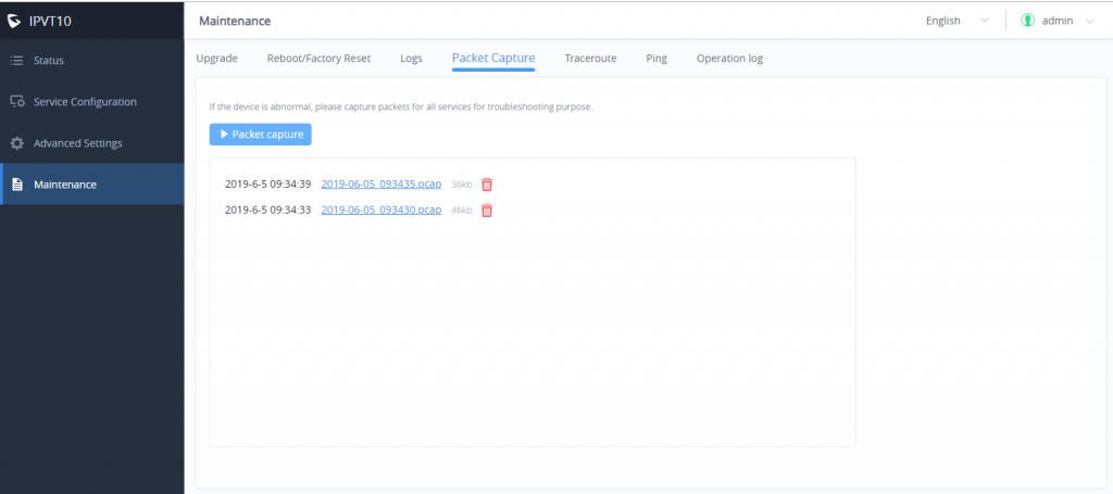
3. Click on the “Packet capture” option to start capturing in the IPVT10 server.
4. Click on the icon ![]() to stop capturing the trace, and the trace file will be shown up on the menu below.
to stop capturing the trace, and the trace file will be shown up on the menu below.
5. Click on the file name, such as ![]() to download the trace to the user’s PC. If the traces are too many items in the IPVT10 server, the user could click on the icon
to download the trace to the user’s PC. If the traces are too many items in the IPVT10 server, the user could click on the icon ![]() to delete a certain trace file.
to delete a certain trace file.
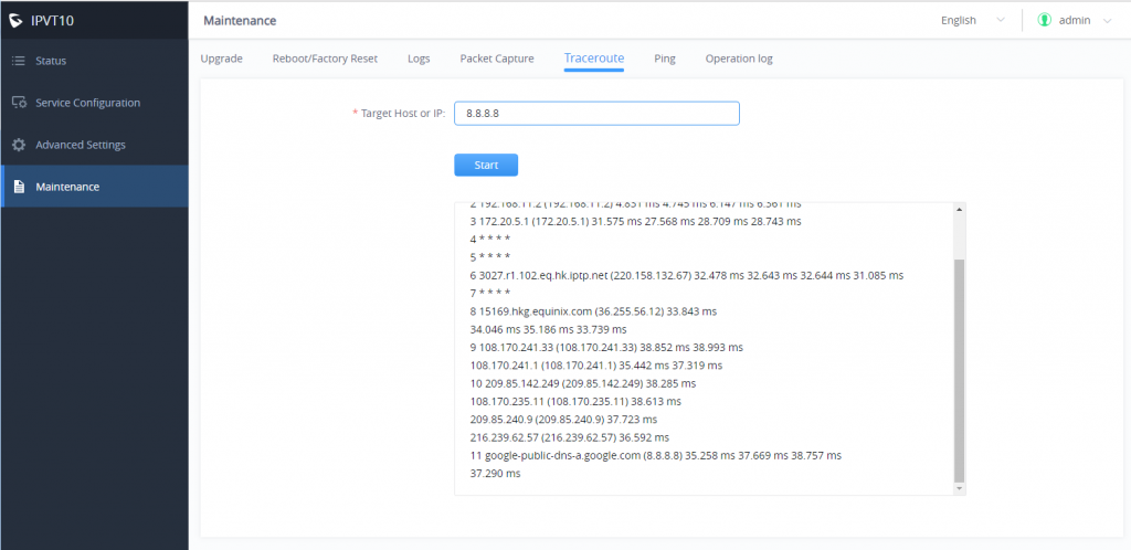
Traceroute
Users could perform a traceroute by entering the target host in the hostname or IP address. Then press the “Start” button. The output result will dynamically display in the window below:
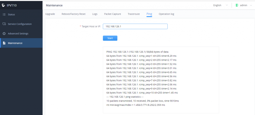
Ping
Enter the target host in hostname or IP address. Then press the “Start” button. The output result will dynamically display in the window below.
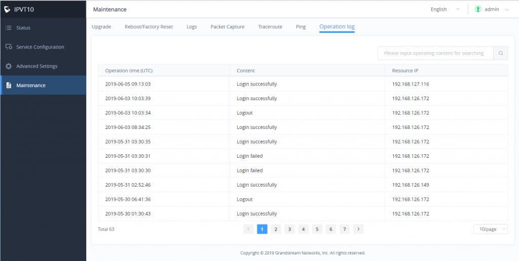
Operation Logs
Users can view all the operation logs on the “Maintenance” page. All the operations on the service platform are displayed here, such as login, deployment service, restart service, factory reset, firmware upgrade, license modification, packet capture, etc.
TYPICAL NETWORK SOLUTIONS
Users could select the network solutions based on the actual requirements. There are several scenarios:
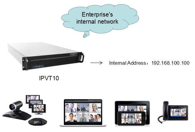
Scenario 1: Internal Network
The server is deployed on the internal network. The users use the service via an internal network. Users need to configure the internal network IP address for the server. If users register accounts and start conferences on the internal network, and other participants are all on the internal network, users could only deploy the server on the internal network, and only configure the internal network adapter. For example, users could configure this server in private networks.
Scenario 2: External Network
The server is deployed on the external network. Users could access the server via the public network. Users need to configure the external network IP address in the server. If users register accounts and start conferences on the public network, and other participants are all on the public network, users could only deploy the server on the public network and configure the public network adapter.
Scenario 3: External Users to Internal Server
The server is deployed on the internal network for external users. The users need to use the service via the public network. In this case, users need to configure the external network IP address and static NAT in the server. If the server is deployed on the internal network, and all participants need to use the service via a public network, users need to configure the static NAT to ensure that certain public networks can access the server. Users could configure the External Network Adapter and NAT to complete the configuration. This deployment does not support users to access the server directly via the internal network. Otherwise, it may cause abnormal issues for the conferences.
Scenario 4: Internal Network and External Network
The server is deployed on the internal network. The users could access and use the service via either an internal network or an external network. In this case, users need to configure both the internal network and external network in the server and routing rules. Users need to configure both Internal Network Adapter and External Network Adapter.
Scenario 5: Internal Network and some External Users
The server is deployed on the internal network. Users could access and use the service via an internal network and limit certain public IP addresses to be able to access the server. In this case, users must configure 2 networks (An internal network and an external network with NAT), and the routing rules. The server’s private network address can be configured via static NAT to allow certain external users to access the server.
CONFIGURE GVC32XX CONFERENCE CLIENTS
Configure Service IP Address
Before a conference starts on the GVC32xx client, the user must configure the IP address of the IPVideoTalk server. Please, refer to the following steps for the IP address of IPVideoTalk.
- Start the GVC32xx device, and ensure to connect the GVC32xx client to the network correctly
- Click on the IPVideoTalk application.
- Select the “Settings” icon
 , and go to the configuration as shown below:
 - Input the “IPVideoTalk Server” address which is the IP address of the IPVT10 server.
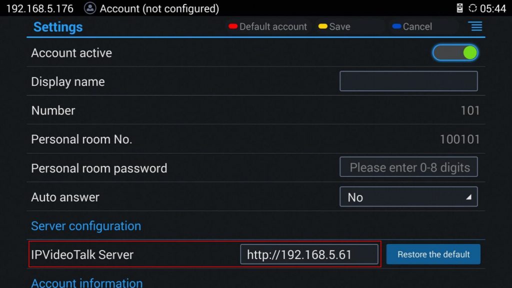
5. Click to save the configuration, and the device will connect to the IPVideoTalk server automatically. The device will be automatically assigned an IPVideoTalk ID, starting from “100”. If the IPVideoTalk ID status icon turns green, that means the account could be used normally.
START CONFERENCES
When the server is configured, users could use the conference client to start conferences.
- Input the domain name or IP address of the IPVT10 server in the browser.
2. log in to the Conference Management Platform with the credentials (The default username and password are admin/admin, and users could configure the new username/password on IPVT10’s Web UI).
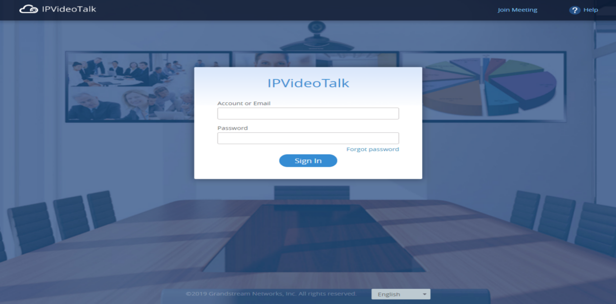
3. Users could schedule meetings and check the meeting histories on the Meeting Management Platform, as the screenshot shows below:
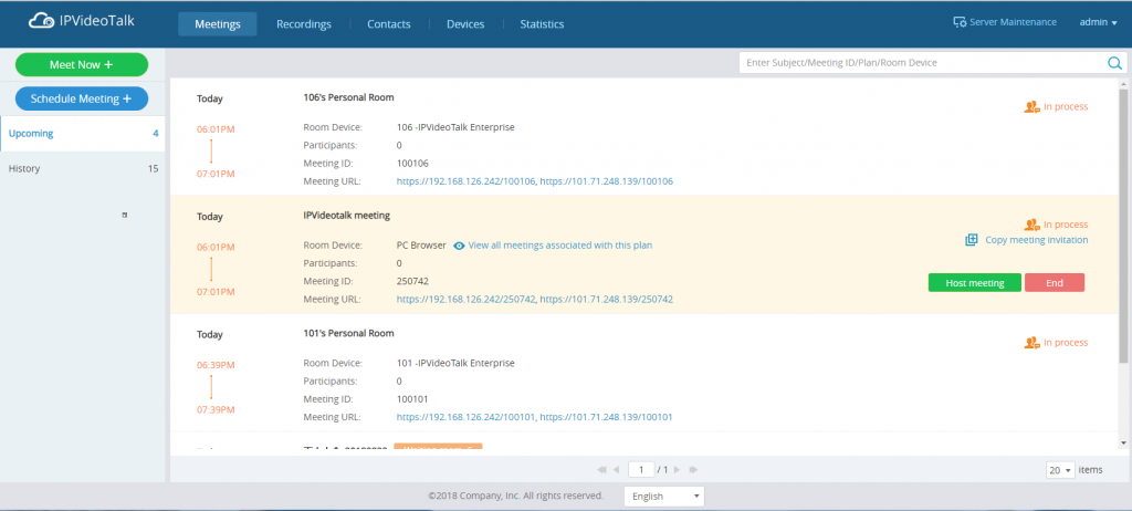
For more information, users could go to Grandstream’s official website https://www.grandstream.com/support and download the User Guide of IPVT10 to get more details.
CHANGELOG
This section documents significant changes from previous versions of the Administration Guide for IPVT10. Only major new features or major document updates are listed here. Minor updates for corrections or editing are not documented here. Users could log in to the product page to get more firmware update logs:
https://www.grandstream.com/support/firmware/
Firmware Version 1.0.6.14
- No Major changes.
Firmware Version 1.0.6.13
Firmware Version 1.0.6.10
- No Major Changes.
- No Major Changes.
- Added support for a new Video Mode option [Video Mode]
- Added support for a new Video Stream option [Video Stream]
- Support setting IVR to Russian Language [Configuring Conference Management Platform Information]
- Supported Spanish IVR if the user changes the default language to Spanish on the management platform. [Configuring Conference Management Platform Information]
- Supported to allow users to configure the dynamic domain name in Network Settings. [Network Settings]
- Supported to custom the host code length of the meeting to 4 – 32 digits. [Length of Host Code]
- Added access restriction feature. The user can add the IP addresses to the white list, and only the IP addresses on the white list can access the deployment management page and meeting management page. [Access Restrictions]
- Add option to “Ignore certificate” that allows the mailbox to send mail if the SMTP server is a self-signed certificate. [Ignore certificate]
- No Major Changes.
- Added ability to configure video bitrate type and video bit rate.
- No Major Changes.
- No Major Changes.
- Added support for Google Speech Recognition service. [Third Party Speech Recognition Service Configuration]
- Added support for alarm notification email configuration. [Alarm Email Setup]
- Added support for static defense settings.
- Added support for operation logs viewing. [Operation Logs]
- Added support for the Fail2Ban feature.
- Added support for Ping and Traceroute troubleshooting tools.
- Improve the meeting capacity: Support up to 50 meetings of two parties, or 10 meetings of three parties. Each meeting layout occupies 1 meeting resource. [PRODUCT OVERVIEW]
- Add support H.323. [IPVT10 Technical Specifications]
- Add multiple meeting layout choices for each meeting, also add support meeting caption, sending pictures and files, and NFS extended disk. [IPVT10 Technical Specifications]
- Improve IPVT10 Web UI: Display NFS extended disk, display all sockets status, configure the meeting URL for the public, add displaying system information, and add “Trial” tag on License.
- Add support to send a test email for the SMTP mailbox. [Configure SMTP Mailbox]
- Changing the initial password is mandatory.
- Add support for Video display for terminals registered to UCM that are connected to the IPVT10 server via the trunk. [connect the IPVideoTalk Conference System with a 3rd party platform]
- Add the region management function to the device. [Configure IPVT10 Server Region] [Region Management]
- Added resetting the login password to the default password. [Forgot Password]
- Added Setup wizard for first-time use. [Setup Wizard]
- Added Server Status Dashboard. [Server Status]
- Added support for Cluster Host/Slave server. [Cluster Host Server Configuration] [Configure Slave Server] [Setup Wizard]
- Added support for “Debug” for any troubleshooting needs.
- This is the initial version.