
WELCOME
The GSC3516 is a SIP intercom speaker and microphone that allows offices, schools, hospitals, apartments, and more to build powerful voice intercom solutions that expand security and communication. This robust SIP intercom device offers 2-way voice functionality with both a high fidelity 15W HD speaker and 3 directional microphones with Multichannel Microphone Array Design (MMAD) and 1 omnidirectional auxiliary microphone that offers a 4.2-meter pickup distance. The GSC3516 supports a wide range of peripherals including Bluetooth devices, a built-in whitelist, and blacklists to block unwanted calls easily, integrated dual-band Wi-Fi, and advanced acoustic echo cancellation. By pairing the GSC3516 with other Grandstream devices, including desktop and cordless IP phones as well as the GDS series of Facility Access products, users can easily sculpt a state-of-the-art security and voice intercom solution. Thanks to its modern industrial design, a cleanable exterior surface, and rich features, the GSC3516 is the ideal intercom speaker/microphone for any setting.
The GSC3506 is a 1-way public address SIP speaker that allows offices, schools, hospitals, apartments, and more to build powerful public address announcement solutions that expand security and communication. This robust SIP speaker offers crystal clear HD audio functionality with a high-fidelity 30-Watt HD speaker. The GSC3506 support built-in whitelists, blacklists, and greylists to easily block unwanted calls, SIP and multicast paging, group paging, and PTT. users can easily sculpt a state-of-the-art security and PA announcement solution. Thanks to its modern industrial design and rich features, the GSC3506 is the ideal SIP speaker for any setting.
PRODUCT OVERVIEW
Feature Highlights
The following table contains the major features of the GSC35X6:
GSC3516  |
|
GSC3506  |
|
GSC3516/GSC3506 Features in a Glance
GSC3516 Technical Specifications
The following table resumes all the technical specifications including the protocols/standards supported, voice codecs, telephony features, languages, and upgrade/provisioning settings for GSC3516.
Protocols/Standards | SIP RFC3261, TCP/IP/UDP, RTP/RTCP, RTCP-XR,HTTP/HTTPS, ARP, ICMP, DNS (A record, SRV, NAPTR), DHCP, PPPoE, SSH, TFTP, NTP, STUN, LLDP-MED, SIMPLE, LDAP,TR-069, 802.1x, TLS, SRTP, IPv6, OpenVPN® |
Network Interfaces | One 10/100 Mbps port with integrated PoE/PoE+ |
Operating System | Linux |
Bluetooth | Yes, integrated Bluetooth |
Wi-Fi | Yes, dual-band 2.4 & 5GHz with 802.11 a/b/g/n/ac |
Auxiliary Port | One 2-pin multi-purpose input port, Reset |
Voice Codecs and Capabilities | G.711µ/a, G.722 (wide-band), G.726-32, iLBC, Opus, G.723, G.729A/B, in-band and out-ofband DTMF (In audio, RFC2833, SIP INFO), VAD, CNG, AEC, PLC, AJB, AGC, ANS |
Telephony Features | SIP Paging, Multicast Paging,Group Paging, PTT, Call-waiting with priority override, Bluetooth SCO call |
HD Audio | Yes, HD speakerphone with support for full band audio with 48KHz |
Speaker | 15W high-fidelity HD speaker |
Microphones | 3 directional microphones with beam-forming capability and up to 4.2-meter voice pickup distance and 1 omnidirectional auxiliary microphone |
QoS | Layer 2 QoS (802.1Q, 802.1p) and Layer 3 (ToS, DiffServ, MPLS) QoS |
Security | User and administrator level passwords, MD5 and MD5-sess based authentication, 256-bit AES encrypted configuration file, TLS, SRTP, HTTPS, 802.1x media access control,secure boot |
Multi-language | English, German, French, Spanish, Portuguese, Russian & Chinese |
Upgrade/Provisioning | Firmware upgrade via TFTP / HTTP / HTTPS or local HTTP upload, mass provisioning using GDMS/TR069 or AES encrypted XML configuration file |
Power & Green Energy Efficiency | Integrated PoE* 802.3af Class 3, PoE+ 802.3at Class 4 |
Temperature and |
|
Package Content |
|
Physical Specifications |
|
Compliance |
|
GSC3506 Technical Specifications
The following table resumes all the technical specifications including the protocols/standards supported, voice codecs, telephony features, languages, and upgrade/provisioning settings for GSC3506.
Protocols/Standards | SIP RFC3261, TCP/IP/UDP, RTP/RTCP, RTCP-XR,HTTP/HTTPS, ARP, ICMP, DNS (A record, SRV, NAPTR), DHCP, PPPoE, SSH, TFTP, NTP, STUN, LLDP-MED, SIMPLE, LDAP,TR-069, 802.1x, TLS, SRTP, IPv6, OpenVPN® |
Network Interfaces | One 10/100 Mbps port with integrated PoE/PoE+ |
Operating System | Linux |
Auxiliary Port |
|
USB Port | USB2.0, External USB used for storage purposes. |
Voice Codecs and Capabilities | G.711µ/a, G.722 (wide-band), G.726-32, iLBC, Opus, G.723, G.729A/B, in-band and out-ofband DTMF (In audio, RFC2833, SIP INFO), VAD, CNG, PLC, AJB |
Telephony Features | SIP Paging, Multicast Paging,Group Paging, PTT, Call-waiting with priority override. |
HD Audio | Yes, HD speakerphone with support for full band audio with 48KHz |
Speaker | 30W high-fidelity HD speaker |
QoS | Layer 2 QoS (802.1Q, 802.1p) and Layer 3 (ToS, DiffServ, MPLS) QoS |
Security | User and administrator level passwords, MD5 and MD5-sess based authentication, 256-bit AES encrypted configuration file, TLS, SRTP, HTTPS, 802.1x media access control,secure boot |
Multi-language | English, German, French, Spanish, Portuguese, Russian & Chinese |
Upgrade/Provisioning | Firmware upgrade via TFTP / HTTP / HTTPS or local HTTP upload, mass provisioning using GDMS/TR069 or AES encrypted XML configuration file |
Power & Green Energy Efficiency | Integrated PoE* 802.3af Class 3, PoE+ 802.3at Class 4 |
Temperature and |
|
Package Content |
|
Compliance |
|
GSC3506 Technical Specifications
GETTING STARTED
This chapter provides basic installation instructions including the list of the packaging contents and also information for obtaining the best performance with the GSC3516/GSC3506.
Equipment Packaging
GSC3516

1x GSC3516 Main Case. |
1x Metal Bracket |
1x Plastic Bracket |
Hang rope plate |
4x Screw (PM 3x50) |
3x Screw (PA 3.5x20) |
Wiring Seat |
3x Plastic Expansion Bolt |
3x M3 NUT |
1x Quick Installation Guide |
Equipment Packaging
GSC3516 Ports

1 | 2-PIN Port | 2-PIN Multi-Purpose Input Port. |
2 | NET/PoE | Ethernet RJ45 port (10/100Mbps) supporting PoE/PoE+. |
3 | RESET | Factory reset pinhole. Press for 10 seconds to reset factory default settings. |
Ports Description
GSC3506

1x GSC3506 |
1x Mounting Hole Cut-Out Template |
1x Quick Installation Guide |
GSC3506 Ports and buttons

1 | USB Port | USB2.0, External USB Storage. |
2 | NET/PoE | Ethernet RJ45 port (10/100Mbps) supporting PoE/PoE+. |
3 | 2-PIN Port | 2-pin switch-in input port |
4 | RESET | Factory reset button. |
5 | Volume | Sound Volume buttons. |
LED Indicators
The GSC35X6 contains 4 types of colored LEDs (Red, Green, White and Blue light) that are used in some specific situations and operations. Please, refer to the following table describing each one of the LED Indicators’ statuses:
Color | LED Indicator Status | Description |
Red Light | Fast Flashing (every 1s) | Rebooting/factory resetting |
Slow Flashing (On 1s, Off 2s) | Unhandled event: (Included Missed call(s), new voice mails, new SIP messages). Note: In case it's connected via Bluetooth, Missed Call/Voicemail Red LED will not light and will remain flashing in blue. | |
Solid Red | The contacts/storage space is full | |
Green Light | Fast Flashing (every 1s) | Incoming calls / outgoing call (only for GSC3516) |
Slow Flashing (On 1s, Off 2s) | Call on hold. | |
Solid Green | During the call. | |
White Light | Fast Flashing (every 1s) | Upgrading the firmware. |
Blue Light | Fast Flashing (every 1s) | Bluetooth pairing. ( only for GSC3516) |
LED Indicators
Hardware Installation
GSC3516 Hardware installation
GSC3516 can be mounted on the wall or ceiling. Please refer to the following steps for the appropriate installation :
Wall Mount
- Locate the equipment holder in the desired position with the arrow up. Drill three holes on the wall referring to the positions of holes on the metal bracket.
- Fix the metal bracket on the wall with expansion screws.
- Align the position line on the device’s back cover with the positioning slot.
- Rotate the device clockwise until it is locked in the right position.

Ceiling Mount
- Put the ceiling mounting (metal bracket) in the ceiling’s center and mark the position of the three screw holes.
- Drill a round hole with a diameter of 18mm for the Ethernet cable. The distance between its center and the highlighted hole on the plastic bracket should be 35mm.
- Fix the plastic and metal brackets on the ceiling with flat-head screws and locknuts. Then place an Ethernet cable pass through the 18mm-round hole.
- Align the position line on the device’s back cover with the positioning slot.
- Rotate the device clockwise until it is locked in the right position.

Anti-theft Installation
After the device is assembled with the metal bracket support on the wall or ceiling, use the anti-detachable screw (M3 x 50) in order to prevent theft.

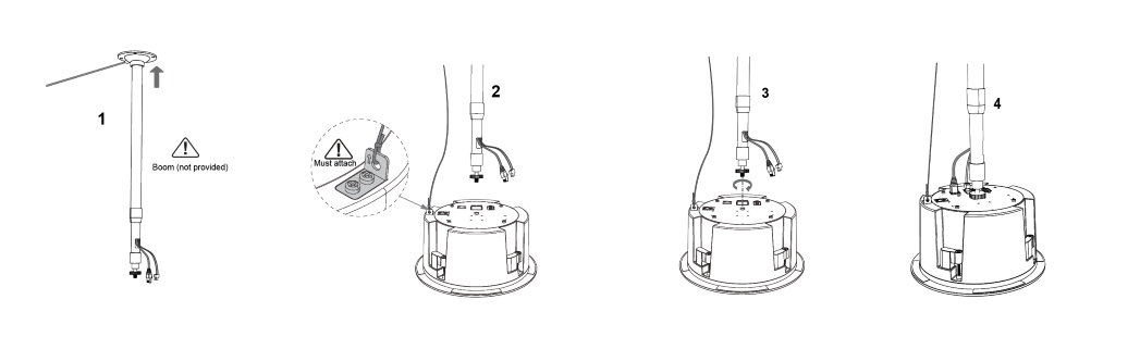
GSC3506 Hardware installation
GSC3506 can be mounted on the ceiling or the Boom. Please refer to the following steps for the appropriate installation.
Ceiling Mount
- Drill a round hole with a diameter of 230mm or use the Mounting Hole Cut-Out Template.
- To ensure safety, install first the anti-fall ropes, then plug in the Ethernet and 2-pin cables.
- Open the front cover with a flat-head screwdriver.
- Align the device with the hole and push it up slowly with two hands.
- Use a screwdriver and gently rotate clockwise the screws marked as (1), (2), (3), and (4) in the step 5 illustration.
- Align the notch on the front cover with the notch on the device, and press the whole front cover to ensure that each buckle is fastened.

Boom Mount
- Fix the Boom in the ceiling.
- To ensure safety, install first the anti-fall ropes.
- Attach the Boom with the GSC3506 ceiling hole and rotate to fix it in place.
- Plug in the Ethernet and 2-pin cables.
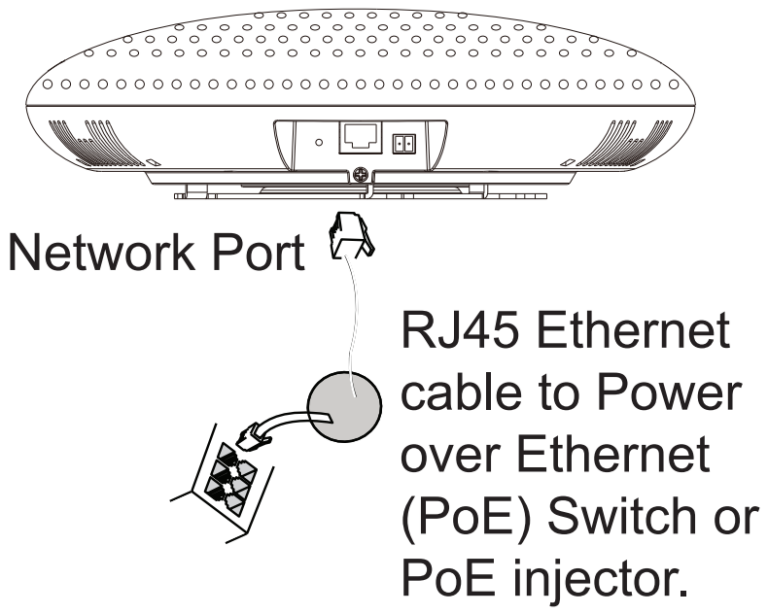
Powering and Connecting GSC3516
The GSC3516 can be powered on using PoE/PoE+ switch or PoE injector using the following steps:
- Step 1: Plug an RJ45 Ethernet cable into the network port of the GSC3516.
- Step 2: Plug the other end into the power over Ethernet (PoE) switch or PoE injector.
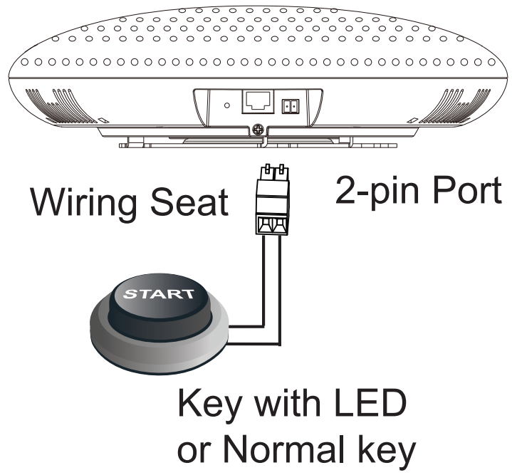
Connecting Wiring Seat for GSC3516
GSC3516 support to connect a “Key & LED” or “Normal Key” to the 2-pin port via Wiring Seat using the following steps:
- Step 1: Take the wiring seat from the install kits.
- Step 2: Connect the “Key & LED” or “Normal Key” with the wiring seat (as shown in the figure below)
Note: This port supports the parallel connection of an incandescent lamp (with less than 1W) or an LED lamp (with less than 100mA).
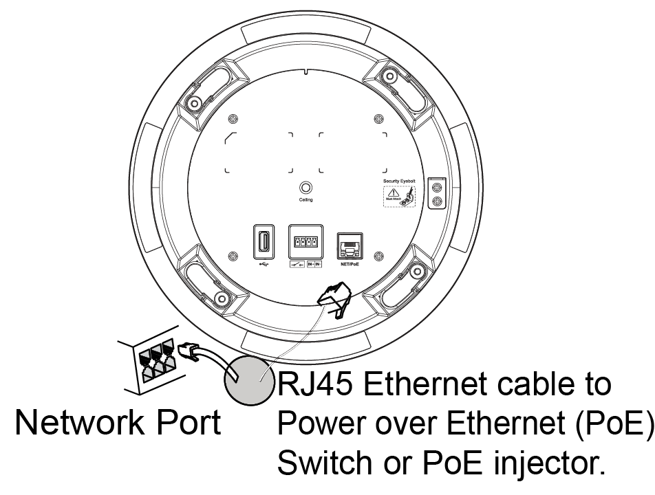
Powering and Connecting GSC3506
GSC3506 can be powered on using PoE/PoE+ switch or PoE injector using the following steps:
Step 1: Plug an RJ45 Ethernet cable into the network port of the GSC3506.
Step 2: Plug the other end into the power over Ethernet (PoE) switch or PoE injector.
Connecting Wiring Seat for GSC3506
GSC3506 support connecting a “Normal Key” to a 2-pin port via Wiring Seat.
Step 1: Take the wiring seat from the install kits.
Step 2: Connect the Normal Key with the wiring seat (as shown in the illustration below).

Access GSC35X6 Web GUI
The GSC3516/GSC3506 embedded Web server responds to HTTP/HTTPS GET/POST requests. Embedded HTML pages allow users to configure the application phone through a Web browser such as Microsoft’s IE, Mozilla Firefox, Google Chrome and etc.
Users can use a computer connected to the same network as the GSC3516/GSC3506 to discover and access the GSC3516/GSC3506 Configuration Interface using its MAC Address.
Please, refer to the following steps in order to access the GSC3516/GSC3506 Web GUI:
- Locate the MAC address on the MAC tag of the unit, which is on the underside of the device, or on the package.
- From a computer connected to the same network as the GSC3516/GSC3506, type in the following address using the GSC3516/GSC3506’s MAC address on your browser: https://gsc_<mac>.local
Example: if a GSC3516/GSC3506 has the MAC address C0:74:AD:xx:xx:xx, this unit can be accessed by typing https://gsc_c074adxxxxxx.local on the browser.
GSC35X6 APPLICATION SCENARIOS
GSC3516 SIP Multicom Intercom System
GSC3516 can be used as an Intercom System using built-in SIP accounts, once the SIP account is registered the device can receive paging/intercom calls and it will automatically answer calls coming from whitelisted numbers.
While the GSC3506 works as a 1-way SIP speaker with a built-in Intercom system.
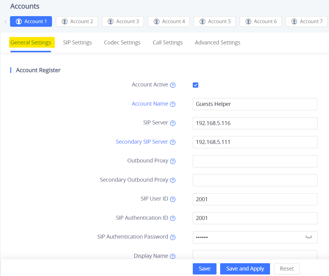
To register a SIP account on the GSC3516/GSC3506 the user needs to go under Account 🡪 Account X 🡪 General Settings, and enter the account information as below, then save and apply the configuration.
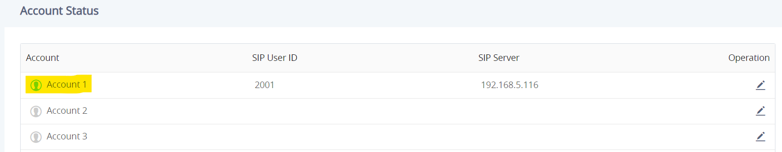
Once the account is registered correctly, the GSC3516/GSC3506 will show the account status under Status 🡪 Account Status.
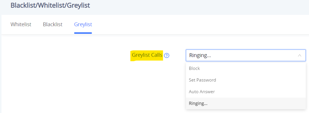
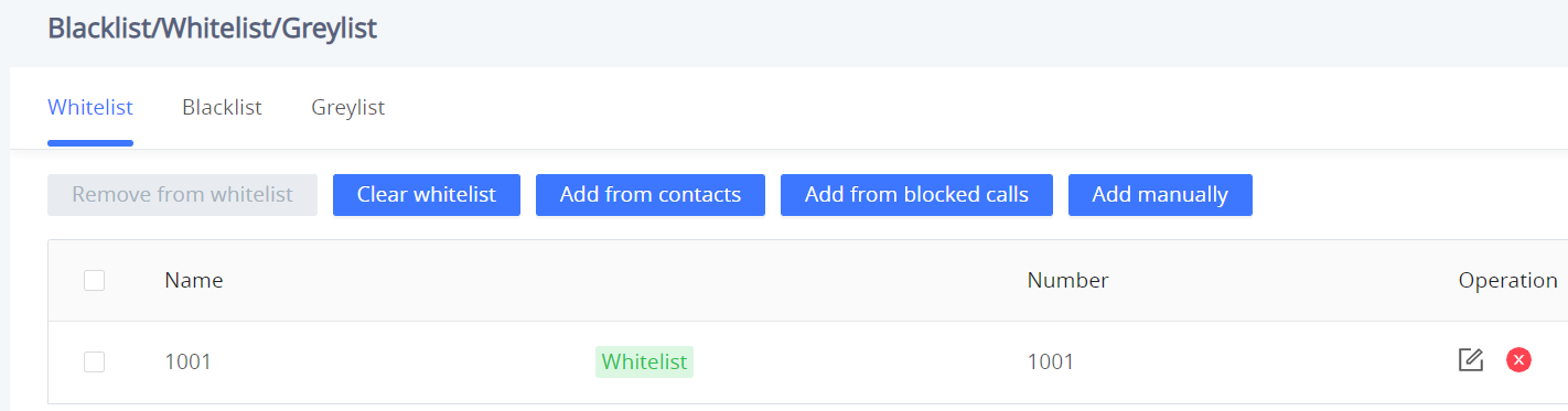
By default, the GSC3516/GSC3506 Blocks non-whitelisted numbers under Calls → Blacklist/Whitelist/Greylist → Greylist, user needs to either allow Non-White list calls or set up a Whitelist that contains the number that will be allowed to call the GSC3516/GSC3516.
On the screenshot below, only number 1001 is allowed to call GSC3516/GSC3506:
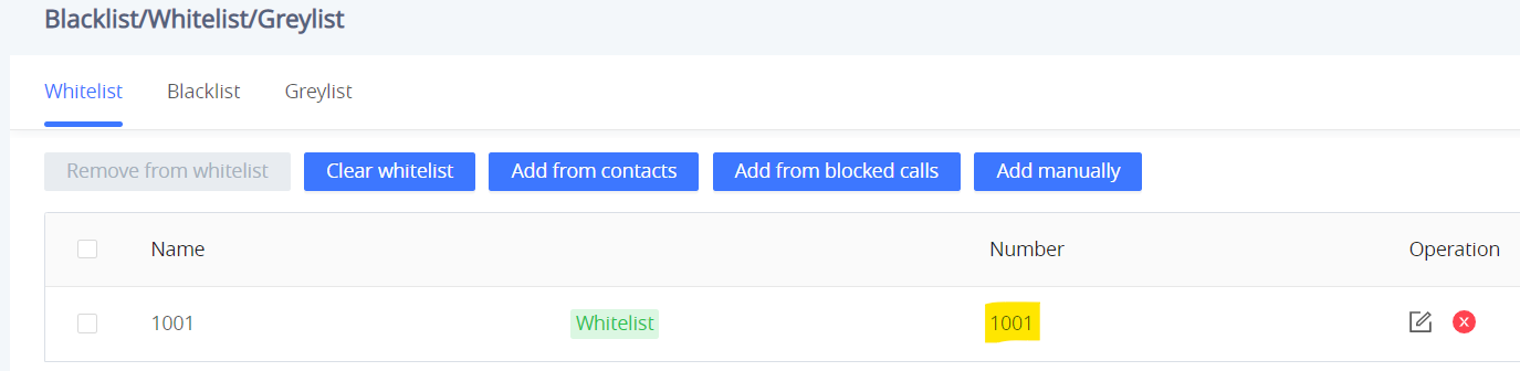
As soon as a SIP call is received by the GSC3516/GSC3506, it first checks if the Caller ID number is allowed on the Whitelist and then answers automatically.
Multicast Paging Application
Multicast paging is an approach to let different SIP users listen for paging calls from a common multicast IP address. In multicast page calls, an audio connection will be set up from sender to receiver, but the receiver will be only able to receive audio, a one-way communication. The 2 entities, Sender/Receiver, must be located on the same LAN (same broadcast domain).
To receive a multicast page, GSC3516/GSC3506 must be well configured to listen to the right address and port. The configuration is located under Phone Settings → Multicast/Group Paging. Up to 10 listening addresses are supported with priority levels from 1 to 10.
Note: Multicast paging configuration requires a reboot to take effect.
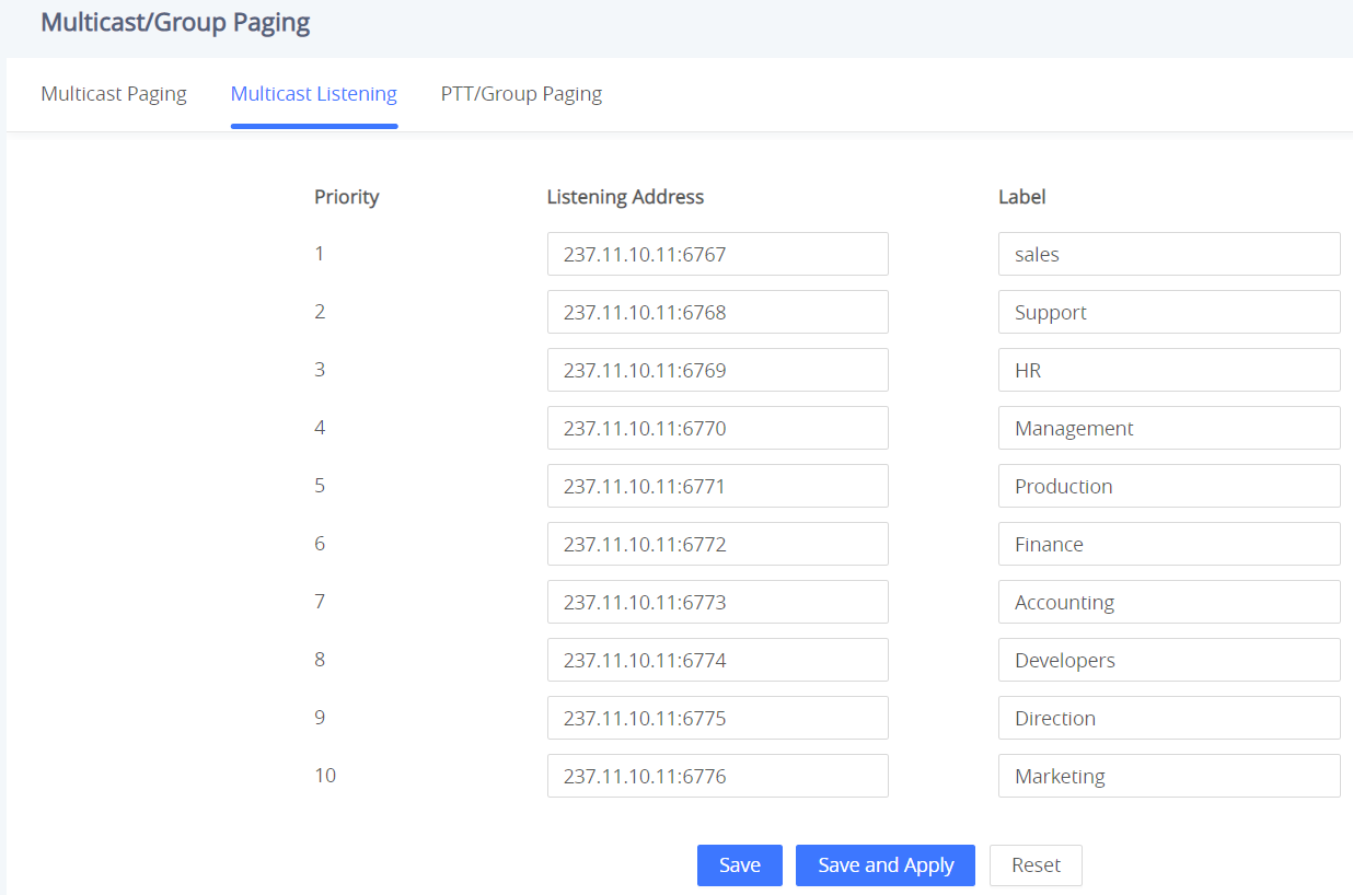
In the above screenshot, the Listening Address “237.11.10.11:6767” with the label “Sales” has the highest priority.
Users can enable the “Paging Priority Active” option (under the Multicast Paging tab) to accept incoming paging calls during active multicast paging. The paging call with a higher priority than the active one will be accepted.
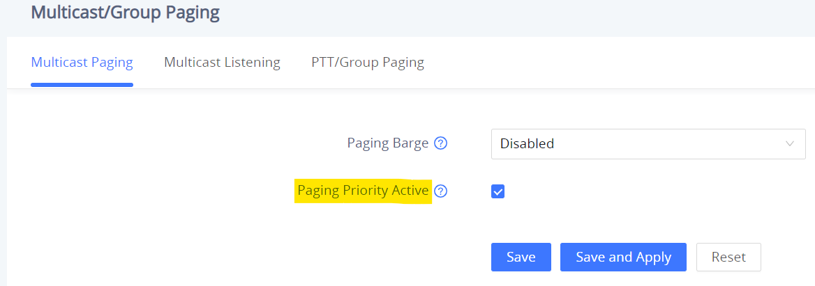
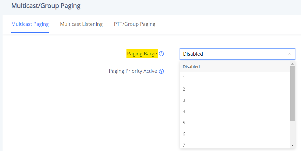
In the case of receiving a multicast paging call while on a unicast SIP call, the GSC3516/GSC3506 can choose to either keep the SIP call or hold this last and allow the multicast call depending on the paging call priority.
This can be set using the “Paging Barge” option. If the option is set to “Disabled” all incoming multicast paging calls will be dropped while on a SIP call. If the multicast paging call has higher priority than the value set on “Paging Barge”, the SIP call will be put on hold and GSC3516/GSC3506 will be the incoming multicast paging.
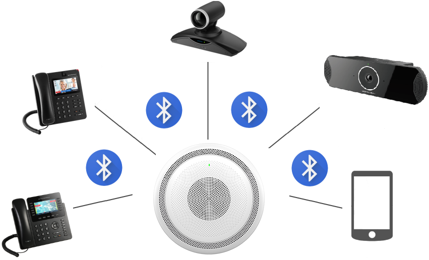
Bluetooth Speaker
The GSC3516 can be used as a Bluetooth speaker for another device and it needs to be connected via Bluetooth to that device. Users need to turn on GSC3516’s Bluetooth function first. The first time when using a new Bluetooth device with the GSC3516, “pair” the device with GSC3516 so that both devices know how to connect securely to each other.
Please, refer to the following steps in order to pair and connect the GSC3516 to the device:
- Go to GSC3516 Web GUI → Network Settings → Bluetooth.
- Enable the “Bluetooth” function, and enable the option “Discoverable to Nearby Bluetooth Devices” in order to make the GSC3516 visible.
- Go to your Device’s Bluetooth settings in order to search for visible devices. The GSC3516 is going to be listed within the visible devices with the “Device Name” configured on the Web GUI.
- Click on the GSC3516 device’s name in order to pair and connect it to the device.
2-pin Multi-Purpose Input Applications
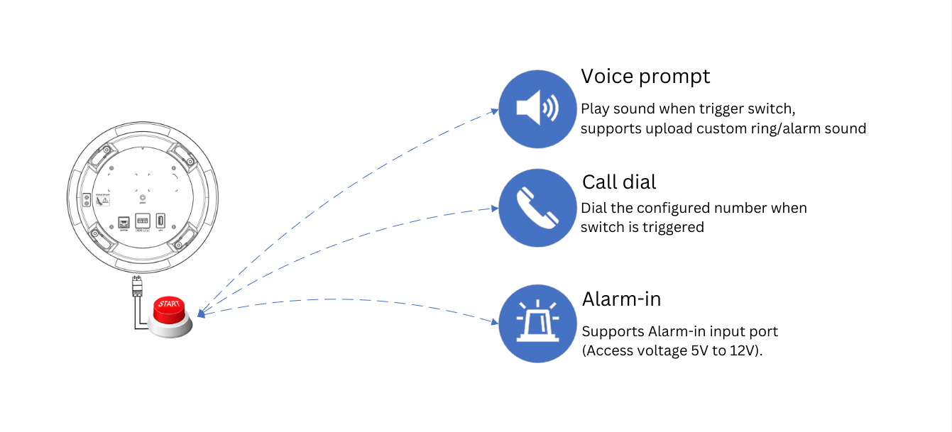
GSC3516 supports 2-pin multi-purpose input that can connect a “Key with LED” or “Normal Key”. By configuring the sensor settings users can enable the GSC3516 to play an audio file (.wav/.mp3 format), and trigger a SIP call to a pre-configured extension.
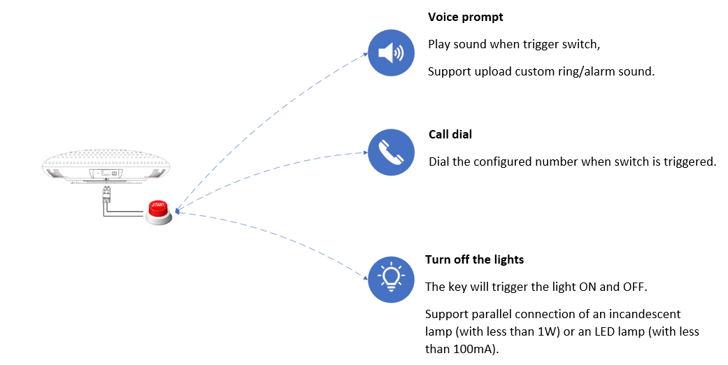
While the GSC3506 supports connecting a “Normal Key” to a 2-pin port via Wiring Seat, By configuring the sensor settings users can enable the GSC3506 to play an audio file (.wav/.mp3 format), and trigger a SIP call to a pre-configured extension, The GSC3506 Model also supports a separate Alarm-in input port (Access voltage 5V to 12V).
To configure sensor settings on Both GSC3516/GSC3506, access web UI → System Settings → Sensor Setting.
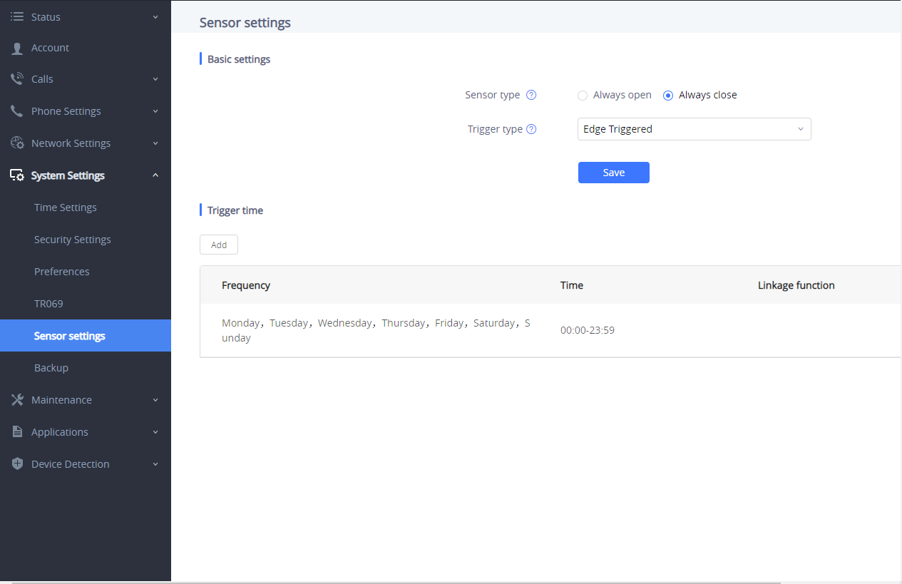
Under the Basic Setting section, users can set “Sensor Type” and “Trigger Type”.
Two states are supported by the Input circuit for the “Sensor Type”:
- Normally Open where the contact is disconnected when there is no electricity
- Normally Close where the contact is connected when there is no electricity.
Users could set “Trigger Type” to:
- Edge Triggered: When selected, the notification is triggered only when the level changes (high level to a low level, or low level to a high level.
- Level Triggered: When selected, only high level (1) will trigger the notification.
Under the “Trigger time” section, users can click on “Add” in order to configure different schedules and a trigger profile for each one as shown in the figure below:
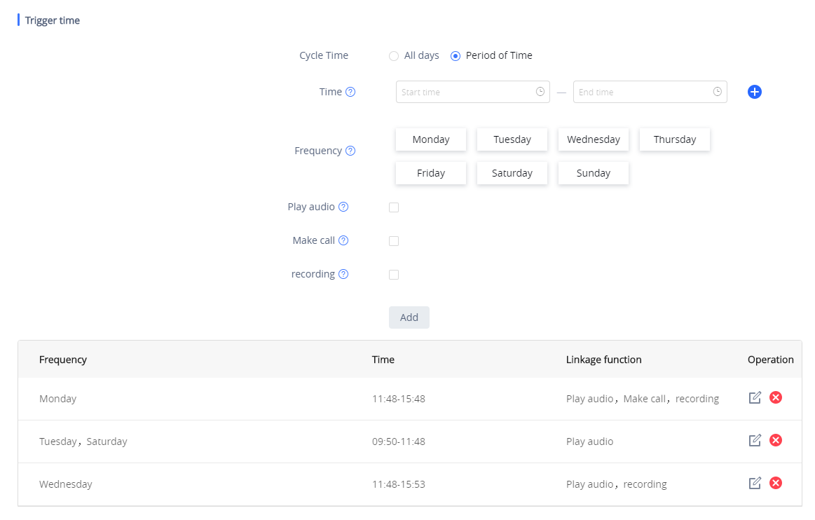
- Cycle Time: The alarm can be configured to be triggered all days of the week, in this case, the “All days” option needs to be checked. Or to some specific days of the week with Start and End times, in this case, the “Period of Time” option needs to be checked for users to be able to configure Time and Frequency options.
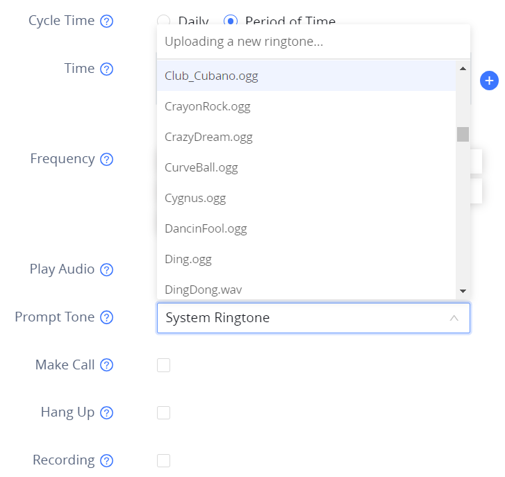
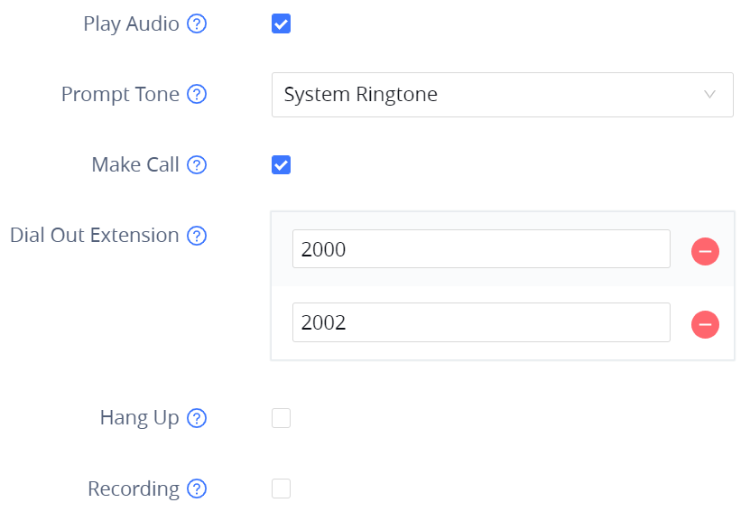
- Play Audio: If checked, GSC3516 will play a sound when the switch is triggered during the schedule. Users can select a “Prompt Tone” from available tones or upload a customized tone.
- Make Call: If checked, GSC3516/GSC3506 will dial out configured numbers on the “Dial out extension” fields (up to 2 numbers supported) when the switch is triggered during the schedule.
GSC35x6 WEB GUI SETTINGS
The GSC35x6 embedded Web server responds to HTTP/HTTPS GET/POST requests. Embedded HTML pages allow users to configure the application phone through a Web browser such as Microsoft’s IE, Mozilla, Firefox, Google Chrome and etc.
Status Page Definitions
Account Status
Account | 16 SIP accounts on the device |
SIP User ID | SIP User ID for the account |
SIP Server | SIP Server Address |
Operation | Edit the account details. |
Account Status
Network Status
Network Status → Ethernet
LAN Port | Displays LAN Port connected or not and the speed |
MAC Address | Global unique ID of device, in HEX format. The MAC address will be used for provisioning and can be found on the label coming with original box and on the label located on the back of the device. |
PPPoE Link Up | PPPoE status: Enabled or Disabled |
IPv4 | |
IPv4 Address Type | Configured IPv4 address type: DHCP, Static IP or PPPoE |
IPv4 Address | IPv4 address of the device. |
Gateway | Default gateway of the device. |
IPv4 NAT Type | Type of IPv4 NAT connection used by the device. |
IPv6 | |
IPv6 Address Type | Configured IPv6 address type: DHCP, Static IP or PPPoE |
Global Unicast Address | IPv6 address of the device. |
Link-Local Address | Link-Local Address of the device |
IPv6 Static Gateway | Default IPv6 gateway of the device. |
IPv6 DUID | IPv6 DUID of the device. |
IPv6 NAT Type | Type of IPv6 NAT connection used by the device. |
Status – Network Status – Ethernet page
Network Status → Wi-Fi ( Available only on GSC3516 )
WLAN MAC Address | Device WLAN MAC Address |
SSID | Displays the name of the SSID currently the device connected to |
Country Code | The configured Country Code |
IPv4 | |
IPv4 Address Type | Configured IPv4 address type: DHCP, Static IP or PPPoE |
IPv4 Address | IPv4 address of the device. |
Gateway | Default gateway of the device. |
IPv4 NAT Type | Type of IPv4 NAT connection used by the device. |
IPv6 | |
IPv6 Address Type | Configured IPv6 address type: DHCP, Static IP or PPPoE |
Global Unicast Address | IPv6 address of the device. |
Link-Local Address | Link-Local Address of the device |
IPv6 Static Gateway | Default IPv6 gateway of the device. |
IPv6 DUID | IPv6 DUID of the device. |
IPv6 NAT Type | Type of IPv6 NAT connection used by the device. |
Status – Network Status – Wi-Fi page
Network Status → DNS & NAT
DNS Server | |
DNS Server x | DNS Server Address up to 4 address (ex: 8.8.8.8) |
DNS Mode | |
Accounts x | DNS Mode for each SIP Account up to 16 accounts: A Record, SRV, NAPTR/SRV, Use Configured IP |
NAT Traversal | |
Accounts x | NAT Traversal for each SIP Account up to 16 accounts: No, STUN, Keep-Alive, UPnP, Auto, VPN (Auto is the default settings) |
Status – Network Status – DNS & NAT page
System Info
System Info → Information
Product Model | Product model of the device: GSC3516 |
Part Number | Product part number |
Software Version | |
Boot | Specifies Boot version |
Core | Specifies Core version |
Prog | Specifies Prog version. This is the main firmware release number, which is always used for identifying the software system |
Locate | Specifies Locale version |
Res | Specifies Locale version |
IP Geographic Information | |
Language | Specifies current language |
Recommend Time Zone | Specifies Recommend Time Zone |
System Time | |
System Up Time | System up time since the last reboot |
System Time | Indicates Date and Time |
System Time Zone | Indicates the Time Zone selected |
PoE Detection | |
PoE Status | Indicates POE Status: Type and Max wattage |
System Information | |
Download System Information | Click on "Downlod" to downlod a file containing all the system information |
System Info – Information page
System Info → Status
Service Status | |
gui | Indicates gui code |
phone | Indicates phone code |
cpe | Indicates cpe code |
avs | Indicates avs code |
User Space | |
User Space Used | Indicates User space used |
Database Status | Indicates the status of the Database (ex: Normal) |
Core Dump | |
Generate core dump | Click on (GUI, AVS, CPE, PHONE) to generate a core dump |
Core Dump | Click on "Download" to download the generated core dump |
Clear Core Dumps | Click on "Start" to clear Core Dumps files |
Special Feature | |
OpenVPN® Support | Indicates the support of OpenVPN® (Yes) |
System Info – Status page
Account Page Definitions
GSC35X6 has 16 independent SIP accounts. Each SIP account has an individual configuration page.
Accounts/General Settings
Account Register | |
Account Active | Indicates whether the account is active. 1st account active by default. |
Account Name | Configures the name associated with each account. |
IP Server | Specifies the URL or IP address, and port of the SIP server. This should be provided by VoIP service provider (ITSP). |
Secondary SIP Server | The URL or IP address, and port of the SIP server. This will be used when the primary SIP server fails. |
Outbound Proxy | Configures the IP address or the domain name of the primary outbound proxy, media gateway or session border controller. It’s used by the device for firewall or NAT penetration in different network environments. If a symmetric NAT is detected, STUN will not work and only an outbound proxy can provide a solution |
Secondary Outbound Proxy | Sets IP address or domain name of the secondary outbound proxy, media gateway or session border controller. The device will try to connect the Secondary outbound proxy only if the primary outbound proxy fails. |
SIP User ID | Configures user account information provided by your VoIP service provider (ITSP). It’s usually in the form of digits similar to phone number or actually a phone number. |
SIP Authentication ID | Configures the SIP service subscriber’s Authenticate ID used for authentication. It can be identical to or different from the SIP User ID. |
SIP Authentication Password | Configures the account password required for the device to authenticate with the ITSP (SIP) server before the account can be registered. After saving, it will appear as hidden for security purpose |
Display Name | Configures the subscriber’s name (optional) that will be used for Caller ID display. |
Tel URI | Indicates E.164 number in “From” header by adding “User=Phone” parameter or using “Tel:” in SIP packets, if the device has an assigned PSTN Number.
Please consult your carrier before changing this parameter. Default is “Disabled”. |
Network Settings | |
DNS Mode | Defines which DNS service will be used to lookup IP address for SIP server’s hostname. There are 4 modes:
To locate the server by DNS SRV set this option to “SRV” or “NATPTR/SRV”. Default setting is “A Record”. |
NAT Traversal | Specifies which NAT traversal mechanism will be enabled on the device. It can be selected from the dropdown list:
If the outbound proxy is configured and used, it can be set to “NAT NO”. If set to “STUN” and STUN server is configured, the device will periodically send STUN message to the STUN server to get the public IP address of its NAT environment and keep the NAT port open. STUN will not work if the NAT is symmetric type.
The default settings is "Auto" |
Proxy-Require | Adds the Proxy-Required header in the SIP message. It is used to
indicate proxy-sensitive features that must be supported by the proxy.
Do not configure this parameter unless this feature is supported on the
SIP server. |
Accounts – General Settings page
Accounts/SIP Settings
Basic Settings | |
SIP Registration | Allows the device to send SIP REGISTER messages to the proxy/server. The default setting is “Yes”. |
UNREGISTER on Reboot | If set to "No", the device will not unregister the SIP user's registration information before new registration. If set to "All", the SIP Contact header will use "*" to clear all SIP user's registration information. If set to "Instance", the device only needs to clear the current SIP user's info |
REGISTER Expiration | Configures the time period (in minutes) in which the device refreshes its registration with the specified registrar. The default setting is 60. The maximum value is 64800 (about 45 days). |
SUBSCRIBE Expiration | Specifies the frequency (in minutes) in which the device refreshes its subscription with the specified register. The maximum value is 64800 (about 45 days). |
Re-Register before Expiration | Specifies the time frequency (in seconds) that the device sends re-registration request before the Register Expiration. The default setting is 0. The range is from 0 to 64,800. |
Registration Retry Wait Time | Configures the time period (in seconds) in which the device will retry the registration process in the event that is failed. The default setting is 20. The maximum value is 3600 (1 hour). |
Add Auth Header on Initial REGISTER | If enabled, the device will add Authorization header in initial REGISTER request. |
Enable OPTIONS Keep-Alive | Enables SIP OPTIONS to track account registration status so the device will send periodic OPTIONS message to server to track the connection status with the server. The default setting is “No”. |
OPTIONS Keep-Alive Interval | Configures the time interval when the device sends OPTIONS message to SIP server. The default value is 30 seconds, in order to send an OPTIONS message to the server every 30 seconds. The default range is 1-64800. |
OPTIONS Keep-Alive Max Tries | Configures the maximum times of sending OPTIONS message consistently from the device to server. Device will keep sending OPTIONS messages until it receives response from SIP server. The default setting is “3”, which means when the device sends OPTIONS message for 3 times, and SIP server does not respond this message, the device will send RE-REGISTER message to register again. The valid range is 3-10. |
SUBSCRIBE for Registration | When set to "Yes", a SUBSCRIBE for Registration will be sent out periodically. |
Use Privacy Header | Controls whether the Privacy header will present in the SIP INVITE message or not, whether the header contains the caller info:
|
Use P-Preferred-Identity Header | Controls whether the P-Preferred-Identity header will present in the SIP INVITE message or not, whether the header contains the caller info:
|
Add MAC in User-Agent | If set to "Yes except REGISTER", all outgoing SIP messages will include the device's MAC address in the User-Agent header, except for REGISTER and UNREGISTER. If set to "Yes to All SIP", all outgoing SIP messages will include the device's MAC address in the User-Agent header. If set to "No", the device's MAC address will not be included in the User-Agent header in any outgoing SIP messages. |
SIP Transport | Determines which network protocol will be used to transport the SIP message. It can be selected from TCP/UDP/TLS. Default setting is “UDP”. |
Enable TCP Keep-alive | Configures whether to enable TCP Keep-alive for the TCP connection between the terminal and the SIP server. |
Local SIP Port | Determines the local SIP port used to listen and transmit. The default setting is 5060 for Account 1, 5062 for Account 2, 5064 for Account 3, 5066 for Account 4, 5068 for Account 5, and 5070 for Account 6. The valid range is from 5 to 65535. |
SIP URI Scheme When Using TLS | Defines which SIP header, “sip” or “sips”, will be used if TLS is selected for SIP Transport. The default setting is “sip”. |
Use Actual Ephemeral Port in Contact with TCP/TLS | Determines the port information in the Via header and Contact header of SIP message when the device use TCP or TLS. If set to No, these port numbers will use the permanent listening port on the device. Otherwise, they will use the ephemeral port for the particular connection. The default setting is “No”. |
Support SIP Instance ID | Determines if the device will send SIP Instance ID. The SIP instance ID is used to uniquely identify the device. If set to “Yes”, the SIP Register message Contact header will include +sip.instance tag. Default is “Yes”. |
SIP T1 Timeout | Defines an estimate of the round-trip time of transactions between a client and server. If no response is received in T1, the figure will increase to 2*T1 and then 4*T1. The request re-transmit retries would continue until a maximum amount of time define by T2. The default setting is 0.5 sec. |
SIP T2 Timeout | Specifies the maximum retransmit time of any SIP request messages (excluding the SIP INVITE message). The re-transmitting and doubling of T1 continues until it reaches the T2 value. The default setting is 4 sec. |
SIP Timer D Interval | Defines the amount of time that the server transaction can remain when unreliable response (3xx-6xx) received. The valid value is 0-64 seconds. The default value is 0. |
Outbound Proxy Mode | Configures whether to put the Outbound Proxy in the Route header, or if SIP messages should always be sent to Outbound Proxy. |
Enable 100rel | Actives PRACK (Provisional Acknowledgment) method. PRACK improves the network reliability by adding an acknowledgement system to the provisional Responses (1xx). It is set to “Yes”, the device will response to the 1xx response from the remote party. Default is “No”. |
Session Timer | |
Enable Session Timer | Allows the device to use the session timer, when set to “Yes”, it will be added in the SIP INVITE message to notify the server. |
Session Expiration | Configures the device’s SIP session timer. It enables SIP sessions to be periodically “refreshed” via a SIP request (UPDATE, or re-INVITE). If there is no refresh via an UPDATE or re-INVITE message, the session will be terminated once the session interval expires.
|
Min-SE | Determines the minimum session expiration timer (in seconds) if the device act as a timer refresher. Default is 90. The valid range is from 90 to 64800. |
Caller Request Timer | Sets the caller party to act as refresher by force. If set to “Yes” and both party support session timers, the device will enable the session timer feature when it makes outbound calls. The SIP INVITE will include the content “refresher=uac”. The default setting is “No”. |
Callee Request Timer | Sets the callee party to act as refresher by force. If set to “Yes” and the both parties support session timers, the device will enable the session timer feature when it receives inbound calls. The SIP 200 OK will include the content “refresher=uas”. The default setting is “No”. |
Force Timer | Configures the session timer feature on the device by force.
The default setting is “No”. |
UAC Specify Refresher | As a caller, select UAC to use the device as the refresher, or select UAS to use the callee or proxy server as the refresher. When set to "Omit", the refresh object is not specified. |
UAS Specify Refresher | As a callee, select UAC to use caller or proxy server as the refresher, or select UAS to use the device as the refresher. |
Force INVITE | Sets the SIP message type for refresh the session. If it is set to “Yes”, the Session Timer will be refreshed by using the SIP INVITE message. Otherwise, the device will use the SIP UPDATE or SIP OPTIONS message. Default is “No”. |
Accounts – SIP Settings page
Accounts/Codec Settings
Audio | |
Preferred Vocoder | Lists the available and enabled Audio codecs for this account. Users can enable the specific audio codecs by moving them to the selected box and set them with a priority order from top to bottom. This configuration will be included with the same preference order in the SIP SDP message. |
Codec Negotiation Priority | Configures the device to use which codec sequence to negotiate as the callee. When set to “Caller”, the device negotiates by SDP codec sequence from received SIP Invite; When set to “Callee”, the device negotiates by audio codec sequence on the device. The default setting is “Callee”. |
Use First Matching Vocoder in 200OK SDP | Configures the device to use the first matching codec in the 200OK message. The default value is 0. |
iLBC Frame Size | Sets the iLBC (Internet Low Bitrate Codec) frame size if ILBC is used. Users can select it from 20ms or 30ms. The default setting is 30ms. |
G.726-32 Packing Mode | Selects "ITU" or "IETF" for G.726-32 packing mode. |
G.726-32 Dynamic Payload Type | Specifies the G726-32 payload type, and the valid range is 96 to 127. The default setting is “127”. |
Opus Payload Type | Defines the desired value (96-127) for the payload type of the Opus codec. The default value is 123. |
Send DTMF | Specifies the mechanism to transmit DTMF digits.
The default settings: via RTP(RFC2833) |
DTMF Payload Type | Configures the RTP payload type that indicates the transmitted packet contains DTMF digits. Valid range is from 96 to 127. Default value is 101. |
Enable Audio RED with FEC | If set to “Yes”, FEC will be enabled for audio call. The default setting is “No”. |
Audio FEC Payload Type | Configures audio FEC payload type. The valid range is from 96 to 127. The default value is 121. |
Audio RED Payload Type | Configures audio RED payload type. The valid range is from 96 to 127. The default value is 124. |
Silence Suppression | If set to "Yes", when silence is detected, a small quantity of VAD packets (instead of audio packets) will be sent during the period of no talking. For codec G.723 and G.729 only. Default is not enabled |
Voice Frames per TX | Configures the number of voice frames transmitted per packet. When configuring this, it should be noted that the “ptime” value for the SDP will change with different configurations here. This value is related to the codec used and the actual frames transmitted during the in-payload call. For end users, it is recommended to use the default setting, as incorrect settings may influence the audio quality. The default setting is 2. |
RTP Settings | |
SRTP Mode | Sets if the device will enable the SRTP (Secured RTP) mode. It can be selected from dropdown list:
The default setting is “No”. |
SRTP Key Length | Configures all the AES (Advanced Encryption Standard) key size within SRTP. It can be selected from dropdown list:
If it is set to “AES 128&256 bit”, the device will provide both AES 128 and 256 cipher suites for SRTP. If set to “AES 128 bit”, it only provides 128-bit cipher suite; if set to “AES 256 bit”, it only provides 256-bit cipher suite. The default setting is “AES128&256 bit”. |
Crypto Life Time | Configures whether to enable Crypto Life Time. Default is "Disabled" |
RTCP Destination | Configures a remote server URI where RTCP messages will be sent to during an active call. |
RTCP Keep-Alive method | Configures the RTCP channel keep-alive packet type:
Default is "Receiver Report" |
RTP Keep-Alive method | Configures the RTP channel keep-alive packet type..
Defaut is "RTP Version 1" |
Symmetric RTP | Configures if the device enables the symmetric RTP mechanism. If it is set to “Yes”, the device will use the same socket/port for sending and receiving the RTP messages. The default setting is “No”. |
RTP IP Filter | Receives the RTP packets from the specified IP address and Port by communication protocol. If it is set to “IP Only”, the device only receives the RTP packets from the specified IP address based on the communication protocol; If it is set to “IP and Port”, the device will receive the RTP packets from the specified IP address with the specified port based on the communication protocol. The default setting is “Disable”. |
RTP Timeout (s) | Configures the RTP timeout of the GSC35xx. If the GSC does not receive an RTP packet within the specified RTP time, the call will be automatically disconnected. The default range is 6-600 seconds. If set to 0, this feature is disabled. |
Accounts – Codec Settings page
Accounts/Call Settings
General | |
Play warning tone for Auto Answer Intercom | When this option is enabled, the device will play a warning tone When auto-answering intercom. The default setting is “yes”. |
Send Anonymous | If set to “Yes”, the “From” header in outgoing INVITE messages will be set to anonymous, essentially blocking the Caller ID to be displayed. |
Anonymous Call Rejection | If set to "Yes", anonymous calls will be rejected. Default is "Disabled" |
Call Log | Categorizes the call logs saved for this account. If it is set to “Log All”, all the call logs of this account will be saved.
The default setting is “Log All”. |
Mute on Intercom Answer | If enabled, the phone will mute the mirophone after answer an intercom call via Call-Info/Alert-Info. Default is "Disabled" |
Ring Timeout | Defines the expiration timer (in seconds) for the rings with no answer. The default setting is 60. The valid range is from 10 to 300. |
Incoming Call Rules | Allow to set incoming call rules for each account registered. This configuration will over rule the global incoming call rules. If set to “Block”, all greylist calls will be blocked. If set to “Set password”, all greylist calls will need to enter the correct password before they can be answered. If set to “Auto answer”, all greylist calls will be automatically answered. If set to “Ringing”, all greylist calls will continue to ringing. The default ring time is 60s. You can customize the timeout under the Account 🡺 Call setting 🡺 Ring timeout. The default value is “Disable”. |
Dial Plan | |
Dial Plan Prefix | This parameter can be configured to define the prefix added to each dialed number. |
Bypass Dial Plan | Bypass dial plan on selected items:
Default is "Nothing is selected" |
Dial Plan | Configures the dial plan to establish the expected number and pattern of digits for a telephone number. This parameter configures the allowed dial-plan for the device. Dial Plan Rules:
Example 1: {[369]11 | 1617xxxxxxx} Allow 311, 611, and 911 or any 10-digit numbers with leading digits 1617 Example 2: {^1900x+ | <=1617>xxxxxxx} Block any number of leading digits 1900 or add prefix 1617 for any dialed 7-digit numbers Example 3: {1xxx[2-9]xxxxxx | <2=011>x+} Allow any number with leading digit 1 followed by a 3-digit number, followed by any number between 2 and 9, followed by any 7-digit number OR allow any length of numbers with leading digit 2, replacing the 2 with 011 when dialed. Default: Outgoing – { x+ | +x+ | *x+ | *xx*x+ } Allow any number of digits, OR any number with a leading +, OR any number with a leading *, OR any number with a leading * followed by a 2-digit number and a *. Example of a simple dial plan used in a Home/Office in the US: {^1900x. | <=1617>[2-9]xxxxxx | 1[2-9]xx[2-9]xxxxxx | 011[2-9]x. | [3469]11 } Explanation of example rule (reading from left to right):
Note: In some cases, where the user wishes to dial strings such as *123 to activate voice mail or other applications provided by their service provider, the * should be predefined inside the dial plan feature. An example dial plan will be: {*x+} which allows the user to dial * followed by any length of numbers. |
Ringtone | |
Account Ringtone | Configures ringtone for the account. Default is "System Ringtone" |
Ignore Alert-Info header | Configures to play default ringtone by ignoring Alert-Info header. Default is "Disabled" |
Match Incoming Caller ID | Specifies matching rules with number, pattern or Alert Info text to ring the selected ringtone. There are up to 10 Matching Rules. |
Accounts – Call Settings page
Accounts/Advanced Settings
Security Settings | |
Check Domain Certificates | Sets the device to check the domain certificates if TLS/TCP is used for SIP Transport. The default setting is “No”. |
Validate Certification Chain | Configures whether to validate certification chain, when TLS/TCP is configured for SIP Transport. If this is set to “Yes”, phone will validate server against the new certificate list. The default setting is “No”. |
Validate Incoming SIP Messages | Specifies if the device will check the incoming SIP messages caller ID and CSeq headers. If the message does not include the headers, it will be rejected. The default setting is “No”. |
Allow Unsolicited REFER | It is used to configure whether to dial the number carried by Refer-to after receiving SIP REFER request actively. If it is set to “Disabled”, the device will send error warning and stop dialing. If it is set to “Enabled/Force Auth”, the device will dial the number after sending authentication, if the authentication failed, then the dialing will be stopped. If it is set to “Enabled”, the device will dial up all numbers carried by SIP REFER. The default is “Disabled”. |
Accept Incoming SIP from Proxy Only | When set to “Yes”, the SIP address of the Request URL in the incoming SIP message will be checked. If it doesn’t match the SIP server address of the account, the call will be rejected |
Check SIP User ID for Incoming INVITE | Configures the device to check the SIP User ID in the Request URI of the SIP INVITE message from the remote party. If it doesn’t match the device’s SIP User ID, the call will be rejected. The default setting is “No”. |
Allow SIP Reset | It is used to configure whether to allow SIP Notification message to perform factory reset on the device. The default setting is “No”. |
Authenticate Incoming INVITE | Configures the device to authenticate the SIP INVITE message from the remote party. If set to “Yes”, the device will challenge the incoming INVITE for authentication with SIP 401 Unauthorized response. Default is “No”. |
SIP Realm used for Challenge INVITE & NOTIFY | Configure this item to validate incoming INVITE, but you must enable authenticate incoming INVITE first to make it take effect. You can verify the NOTIFY information for the provision, including check-sync, resync and reboot, but only when SIP NOTIFY authentication enabled first to make it take effect. |
MOH | |
MOH Mode | Configures MOH mode. If set to “Local MOH”, a local MOH audio file needs to be uploaded for this mode to work. |
Upload Local MOH Audio File | Upload Local MOH Audio File. Click to upload audio file from PC. |
Advanced Features | |
Special Feature | Different soft switch vendors have special requirements. Therefore, users may need to select special features to meet these requirements. Users can choose from Standard, Nortel MCS, BroadSoft, CBCOM, RNK, Sylantro, Huawei IMS, Phonepower, UCM Call center, or Zoom. |
Allow Sync Phonebook Via SIP Notify | Allow Sync Phonebook Via SIP Notify |
Accounts – Advanced Settings page
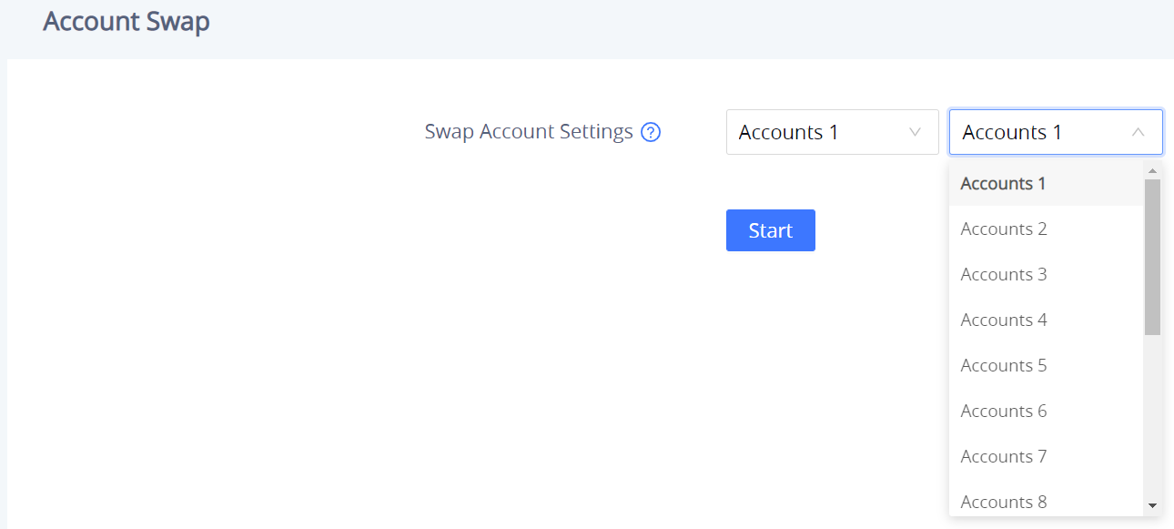
Account Swap
Swap a SIP Account with another one, from 1 to 16, then click on “Start”.
Calls Page Definition
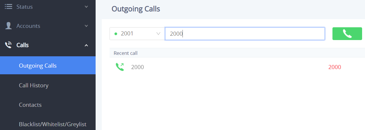
Outgoing Calls
The GSC35X6 allows users to manage their calls using the Click to Dial feature which permits to initiate and receive calls using the Web GUI. To use the Click to Dial feature, please refer the following steps:
- Go under the GSC35X6 Web GUI → Calls → Outgoing Calls
- Select the account to be used.
- Type the number / IP Address to call and press the Dial button
 as displayed in the following screenshots:
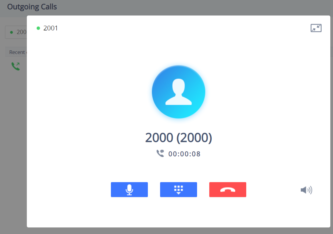
Once the number / IP address is dialed or a Call is received, a window pops up showing the call information and gives the user the ability to do the following operations:
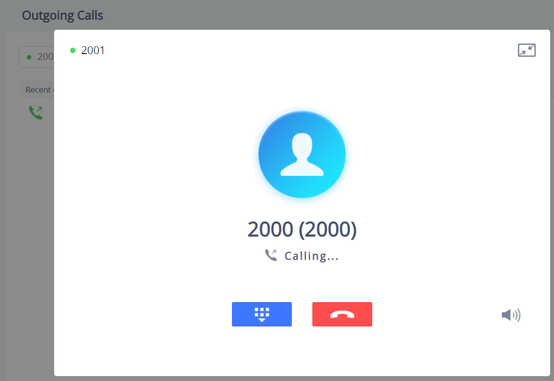
![]() : Reduce the window to a bar at the top of the Web GUI interface.
: Reduce the window to a bar at the top of the Web GUI interface.
![]() : Adjust the ringing volume.
: Adjust the ringing volume.
![]() : Mute the Mic.
: Mute the Mic.
![]() : Start recording the call.
: Start recording the call.
![]() : End the in-progress call.
: End the in-progress call.
Call History
The GSC35X6 Call History is divided into two sections: “Call history” and “Intercepted Record”:
Call history
This section shows all the calls that have been made or answered. Users can find two types of calls under “Call History → Call history”:
![]() Outgoing Calls.
Outgoing Calls.
![]() Answered Calls.
Answered Calls.
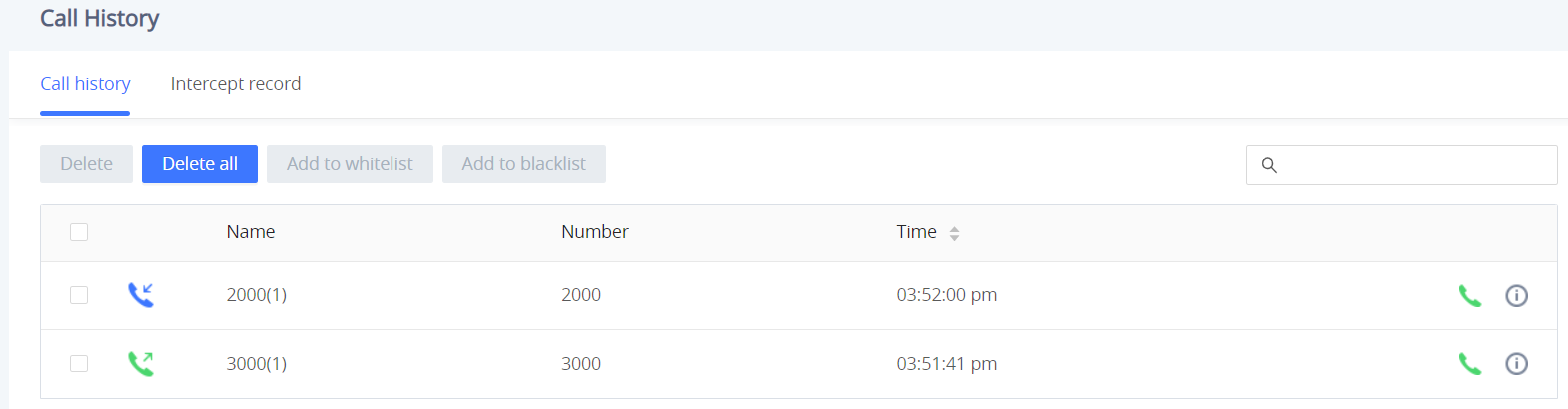
By Tapping on the checkbox to select the call history entries, users can do the following operations:
- Delete Call History: Users need to press the button
 after selecting the call history entries.
 - Add entries to Whitelist: Users may select the entries to be allowed to call the GSC35X6 by clicking on the button
 after selecting the right entries.
 - Add entries to Blacklist: Users can block the calls of some entries by selecting them and pressing the button
 .
.
The following operations can be done as well:
- Make a call to one of the call history entries: Users can directly make a call to a number listed in the call history by clicking directly on the button

- Show calls details: users can show the call details of a number by clicking on the button
 and a window will pop up to show all the calls sent/received with the selected number.
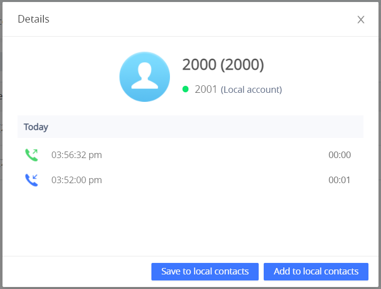
From the Call details window, users can also add the number selected to local contacts by creating a new contact
![]() , or by adding it to an existing contact
, or by adding it to an existing contact
![]() .
.
- Add number to an existing contact: Users can click on “Save to local contacts” in order to show a window with all the contacts already registered in the GSC3516 local contacts and to choose one of the contacts to link the selected number with:
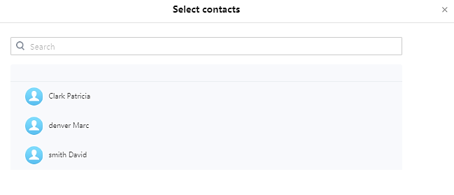
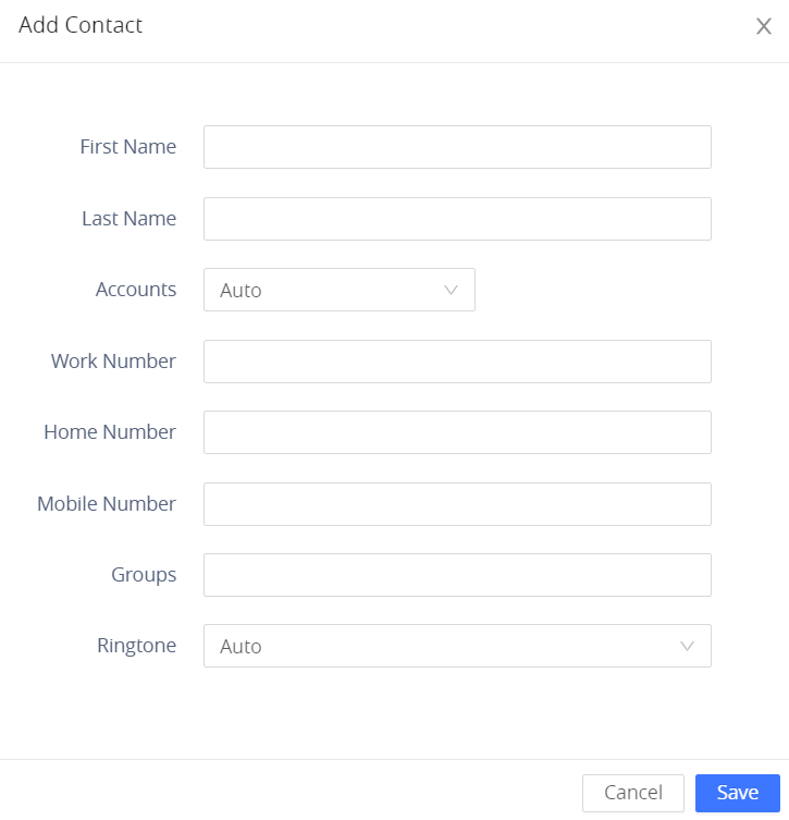
- Create a new contact: user can click on “Add to local contacts” in order to show a window where all the information about the contact needs to be entered.
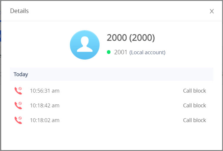
Call History → Intercept Record
This section shows all the calls that have been blocked when received because of not having permission to make a call to the GSC3516. Users can find only one type of call under “Call History → Intercept Record”:
![]() Blocked Calls
Blocked Calls
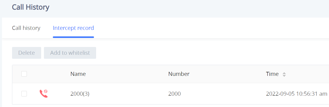
By checking the checkbox to select entries, users can do the following operations:
- Delete Blocked Numbers Call History: Users need to press the button
 after selecting the call history entries.
 - Add entries to Whitelist: Users may select the blocked entries to give them permission to call the GSC3516 by clicking on the button
 after selecting the right entries.
The following operations can be done as well:
- Make a call to one of the entries: Users can directly make a call to a number listed in call history → Intercept Record, by clicking directly on the button

- Show calls details: users can show the call details of a number by clicking on the button
 and a window will pop up to show all the blocked calls received from the selected number.
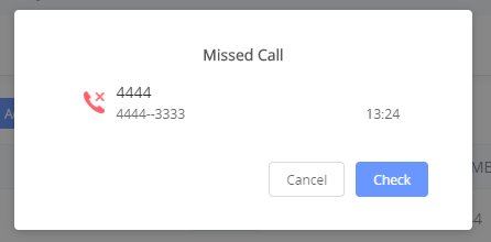
Web GUI Missed Call Notification support
The GSC GUI will display a popup window to notify about missed calls. The figure below contains an example where Extension 4444 couldn’t reach the GSC at 3333.
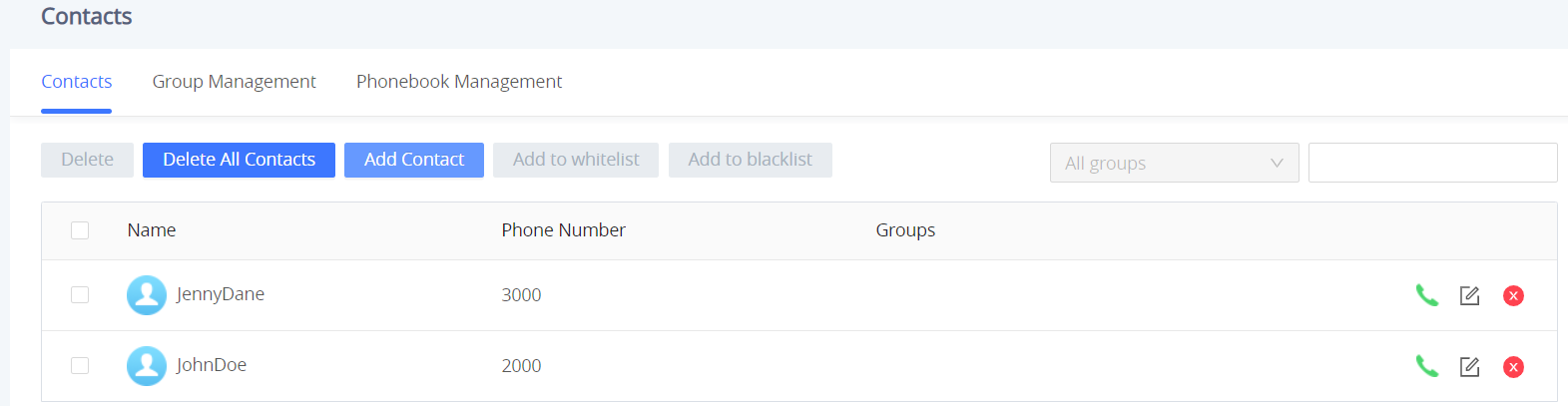
Contacts
-
 Dial Contact.
 -
 Edit contact details.
 -
 : Users can select one or a bench of contacts and click on the “Delete” button in order to delete all the selected contacts.
 -
 : Users can select one or a bunch of contacts and click on the “Add to Whitelist” button in order to directly add the selected contacts to the list of contacts allowed to call the device.
 -
 : Users can select one or a bunch of contacts and click on the “Add to blacklist” button in order to remove the permission to call from the selected contacts.
  : Users can create a new contact by clicking on the “Add Contact” button, then a window pops up (Please, refer to the following figure) in order to enter the new contact’s details.
Group Management
Users could manage the groups of the existing contacts that can be found in “Contacts”.
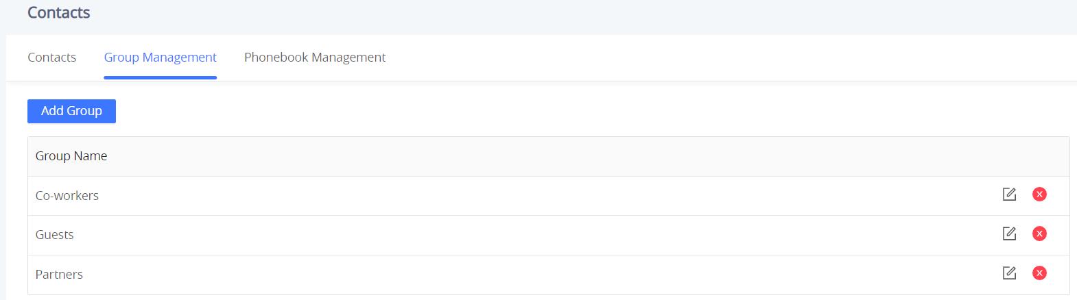
Users have the ability to:
 : Users can click on the “Delete” button in order to delete all the selected groups.
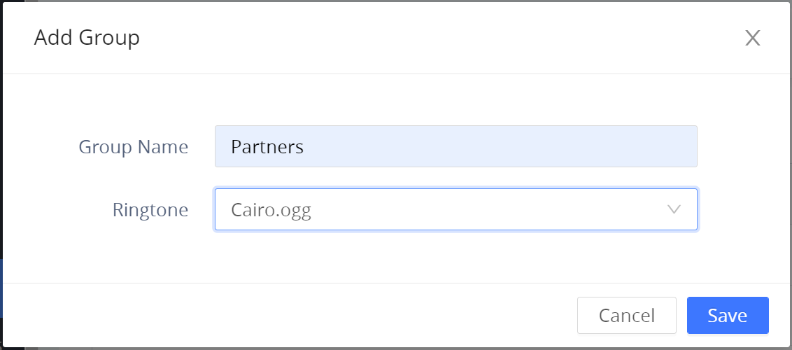
  : Users can create a new group by clicking on the Add Group” button.
Phonebook Management
Enable Phonebook XML Download | Enables Phonebook XML download via HTTP, HTTPS, or TFTP. Default is "Disabled" |
HTTP/HTTPS Username | Enter The username for the HTTP/HTTPS server. |
HTTP/HTTPS Password | Enter The password for the HTTP/HTTPS server. |
Phonebook XML Server Path | Configures the server path to download XML phonebook file. This field could be IP address or URL, with up to 256 characters. |
Phonebook Download Interval | Configures the phonebook download interval (in minutes). If set to 0, automatic download will be disabled. Valid range is 5 to 720. |
Clear Old List When Downloading |
Default is "No" |
Replace Duplicate Items When Downloading |
Default is "No" |
Import Group Method |
Default is "No" |
Sort Phonebook by | Configures to sort phonebook based on the selection of first name, last name or auto:
|
Download XML Phonebook | Click to download the XML Phonebook file |
Upload XML Phonebook | Upload XML Phonebook file to the phone. |
Default Search Mode | Configures the default phonebook search mode:
Default is "Quick Match" |
Contacts – Phonebook Management page
Blacklist/Whitelist/Greylist Settings
This section is for managing calling permissions to the GSC35X6. Users can give or remove permission to call the GSC35X6, this can be managed under the following three subsections:
Whitelist
Users can specify the numbers allowed to call the GSC35X6 and every time a number is added it is listed in the below list:
-
 : Users can remove one or a group of numbers from the whitelist by clicking on the “Remove from Whitelist” button.
Note: Users can also press on to remove one specific contact from the whitelist.
-
 : Users can add the phonebook contacts to the whitelist by clicking on the “Add from contacts” button. A window pops up showing the existing contacts so that users can select the ones wishing to give permission.

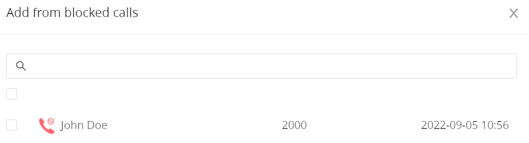
-
 : Users can add the numbers that the GSC35X6 is blocking to the Whitelist by clicking on “Add from blocked calls”. A window pops up showing all the blocked numbers.
-
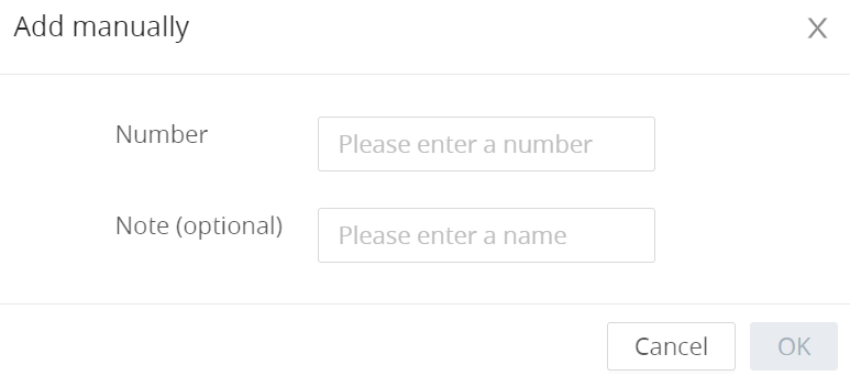
 : Users can add numbers manually to the whitelist by clicking on the “Add manually” button. A window pops up allowing users to enter the number and its name.
Blacklist
Users can specify the numbers to be blocked by the GSC35X6 for incoming calls, and every time a number is added to the blacklist, it is listed in the below list:
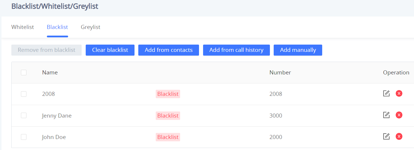
 : Users can remove one or a group of numbers from the blacklist by clicking on the “Remove from blacklist” button.
Note: Users can also press on to remove one specific contact from the blacklist.
-
 : Users can add phonebook contacts to the blacklist by clicking on the “Add from contacts” button. A window pops up showing the existing contacts so that users may select the ones wishing to give permission to
 -
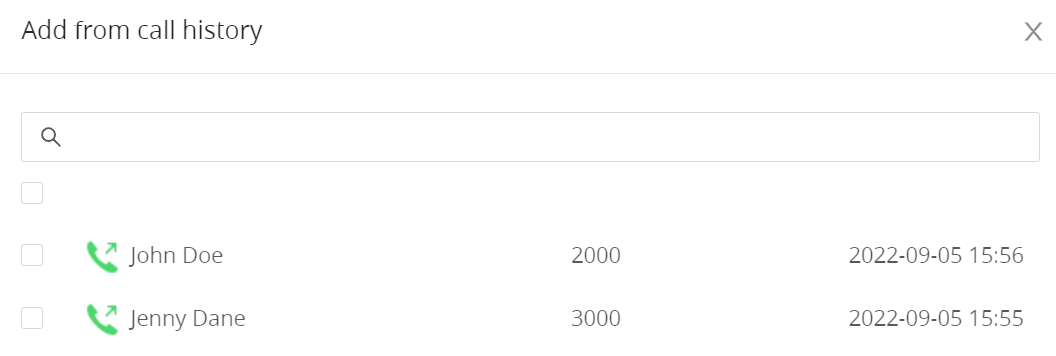
 : Users can add numbers from Call History to the blacklist by clicking on the “Add from call history” button. A window pops up showing all the calls listed in the GSC35X6 call history.
-
 : Users can add numbers manually to the blacklist by clicking on the “Add manually” button.
Greylist
This section allows the user to define the blocking rules for Non-white list calls. The blocking rules available for the users are:
• Block: Configures the GSC35X6 to block all the numbers that are not listed in the Whitelist.
• Auto Answer: Configures the GSC35X6 to allow all the calls received from any number but the number listed in the blacklist.
• Set Password: requires a password before it can be answered.
• Ringing: all greylist calls will continue ringing. The default ring time is 60 s.
Phone Settings Page Definitions
Phone Settings/General Settings
Local RTP Port | Defines the local RTP port pair used to listen and transmit. The default value is 5004. The valid range is from 1024 to 65400. |
Local RTP Port Range | Configures the range of local RTP port. Valid value is from 24 to 10000. |
Use Random Port | Forces the device to use random ports for both SIP and RTP messages. This is usually necessary when multiple phones are behind the same full cone NAT. The default setting is “No”. Note: This parameter must be set to “No” for Direct IP Calling to work. |
Keep-alive Interval | Specifies how the device will send a Binding Request packet to the SIP server in order to keep the “ping hole” on the NAT router to open. The default setting is 20 seconds. The valid range is from 10 to 160. |
STUN Server | Configures the URI of STUN (Simple Traversal of UDP for NAT) server. The device will send STUN Binding Request packet to the STUN server to learn the public IP address of its network. Only non-symmetric NAT routers work with STUN. |
TURN Server Username | Fill in the username to validate TURN server. |
TURN Server Password | Fill in the password to validate TURN server. |
Use NAT IP | Configures the IP address for the Contact header and Connection Information in the SIP/SDP message. It should ONLY be used if it’s required by your ITSP. By default, the box is blank. |
Phone Settings – General Settings
Call Settings
Enable Call Waiting | Enables call waiting feature. If it is disabled, it will reject the second incoming call during an active session without user’s knowledge. But this missed call record will be saved to remind users. The default setting is checked (enabled). |
Enable Call Waiting Tone | Sets to play the call waiting tone along with LED indicator if there is another incoming call. If unchecked, only LED will indicate another incoming call. The default setting is checked (enabled). |
End-Call Tone | If enabled, there will be a prompt tone when the call ends. |
Multicast Tone | If enabled, there will be a prompt tone at the beginning and end of the multicast. |
Automatic Answer Ringing Time (s) | Configures the ring time for the unanswered call. The call will be automatically answered after timeout. Default is 0. |
Busy Tone Ring Time (s) | Configures the timeout for Busy Tone during the call. Default is 30. |
Auto Mute Mode | Configures whether to mute the call on entry automatically.
Note: This function only take effect when the device is from the idle status to call status. Users could click the Mute button on call interface to cancel the current mute status. |
Filter Characters | Sets the characters for filter when dial out numbers. Users could set up multiple characters. For example, if set to “[()-]”, when dial (0571)-8800-8888, the character “()-“ will be automatically filtered and dial 057188008888 directly |
Do Not Escape ‘#’ as %23 in SIP URI | Replaces # by %23 for some special situations. |
Record Mode | Configures phone recording mode
|
Environment | Sets operating environment for the device.
The default value is “Large room & used on empty area”. |
Phone Settings – Call Settings
Ringtone
Auto Config CPT by Region | Configures whether to choose Call Progress Tone automatically by region. If set to “Yes”, the device will configure CPT (Call Progress Tone) according to different regions automatically. If set to “No”, you can manual configure CPT parameters. The default setting is “No”. |
| Configures tone frequencies according to user preference. By default, the tones are set to North American frequencies. Frequencies should be configured with known values to avoid uncomfortable high pitch sounds.
(Frequencies are in Hz and cadence on and off are in 10ms) ON is the period of ringing (“On time” in “ms”) while OFF is the period of silence. In order to set a continuous ring, OFF should be zero. Otherwise it will ring ON ms and a pause of OFF ms and then repeats the pattern. Please refer to the document below to determine your local call progress tones: http://www.itu.int/ITU-T/inr/forms/files/tones-0203.pdf |
Call-Waiting Tone Gain | Adjusts the call waiting tone volume. Users can select “Low”, “Medium” or “High”. The default setting is “Low”. |
Default Ring Cadence | Defines the ring cadence for the device. The default setting is: c=2000/4000. |
Phone Settings – Ringtone
Multicast/Group Paging
Multicast Paging | |
Paging Barge | Sets the threshold of paging calls. If the paging call’s priority is higher than the threshold, the existing call will be hold and the paging call will be answered. Otherwise, the existing call does not be affected. If it is set to Disable (Default), any paging call will not be answered. |
Paging Priority Active | Determines if a new paging call whose priority is higher than the existing paging call will be answered. The default is disabled. Check to enabled. |
Multicast Listening | |
Priority | Configures the IP address and port number for monitoring multicast paging call. Reboot the device to make changes take effect. |
Listening Address | The valid IP address range is from 224.0.0.0 to 239.255.255.255. |
Label | Label for each listening address corresponding to priority. |
PTT/Group Paging | |
General Settings | |
Group Paging Address | Allows to configure the group paging IP address. |
IGMP Keep-alive Interval (s) | Specifies how often the phone reports IGMP when Group Paging function is turned on. IGMP report helps to keep Group Paging alive in sleep state. |
Emergency Group Paging Volume | Configures default volume for group paging when emergency channel/group is used. |
PTT Config | |
PTT | Configures to enable or disable PTT. Default is "Disabled" |
Priority Channel | Set priority channel for PTT. PTT received on priority channel will take precedence over active PTT on normal channel. Priorities go from 1 to 25. |
Emergency Channel | Set emergency channel for PTT. Emergency channel has the highest priority. PTT using emergency channel will take precedence over PTT on priority or normal channel. Please note PTT to emergency channel will not be rejected even when device has enabled DND. |
Accept While Busy | Configures whether to accept PTT while device is in active call. If set to "No", device will ignore PTT while in active call. If set to "Yes", while in active PTT talk, device will accept PTT if it has the same priority; If device is in active SIP call, device will accept PTT and put the SIP call on hold. Default is "Disabled" |
Channel | Configures PTT channel. Configures options for the channel such as transport, accept, join PTT and its label. Only available and joined channel will be displayed in PTT channel list. If users need send or receive PTT, "Transport" and "Accept" must be enabled for this channel. |
Paging Config | |
Group Paging | Allows to enable or disable group paging. |
Priority Group | Configures priority paging group. Paging received on priority group will take precedence overactive paging on normal group. |
Emergency Group | Set emergency group for paging. Emergency group has the highest priority. Paging using emergency group will take precedence over paging on priority or normal group. |
Accept While Busy | Configures whether to accept paging while device is in active call. If set to “No”, device will ignore paging while in active call. If set to “Yes”, while in active paging call, the device will accept other paging calls if it has the same priority. If device is in an active SIP call, device will accept paging and hang up the SIP call. |
Group | Configures paging group. Users can configure whether to use the group to accept and join group, and its label. Only available and joined group will be displayed in paging group list. If users need receive paging, “Subscribe” must be enabled for this group. |
Multicast/Group Paging
Network Settings Page Definitions
Ethernet Settings
Internet Protocol | If IPv4 is selected, the device will be using IPv4 addressing, otherwise, it will be using IPv6 addressing. The default is Prefer IPv4. |
Different Networks for Data and VoIP Calls | Configures whether to set up different networks for the phone data and the call. If set to “Yes”, you need to configure the data network and VoIP network respectively. Note: Reboot is required to take effect. |
IPv4 | |
IPv4 Address Type | Allows users to configure the appropriate network settings on the device. Users could select “DHCP”, “Static IP” or “PPPoE”.
By default, it is set to “DHCP”. |
DHCP VLAN Override | DHCP Option 132 defines VLAN ID and DHCP Option 133 defines priority tag ID. it supports DHCP VLAN override via DHCP Option 132 and DHCP Option 133, or encapsulated DHCP option 132 and DHCP option 133 in DHCP option 43.
By default, it is set to “Disabled” |
Host name (Option 12) | Sets the name of the client in the DHCP request. It is optional but may be required by some Internet Service Providers. |
Vendor Class ID (Option 60) | Configures the vendor class ID header in the DHCP request. Default setting is “Grandstream GSC3516” or “Grandstream GSC3516”. |
| DNS Server 1 | Configures the primary DNS IP address. |
| DNS Server 2 | Configures the secondary DNS IP address. |
| Preferred DNS Server | Configures the Preferred DNS Server. |
Layer 2 QoS 802.1Q/VLAN Tag (Ethernet)
| Assigns the VLAN Tag of the Layer 2 QoS packets for Ethernet. The Default value is 0. Note: When “Different Networks for Data and VoIP Calls” is set to Yes, user needs to set “Layer 2 QoS 802.1Q/VLAN Tag (Ethernet) for Data” and “Layer 2 QoS 802.1Q/VLAN Tag (Ethernet) for VoIP Calls”. |
Layer 2 QoS 802.1p Priority Value (Ethernet)
| Assigns the priority value of the Layer 2 QoS packets for Ethernet. The Default value is 0. Note: When “Different Networks for Data and VoIP Calls” is set to Yes, the user needs to set “Layer 2 QoS 802.1p Priority Value (Ethernet) for Data” and “Layer 2 QoS 802.1p Priority Value (Ethernet) for VoIP Calls”. |
IPv6 | |
IPv6 Address | Configures the appropriate network settings on the device. Users could select “Auto-configured” or “Statically configured”. |
Static IPv6 Address | Enter the static IPv6 address in the “Statically configured” IPv6 address type. |
| IPv6 Prefix Length | Enter the IPv6 prefix length in the “Statically configured” IPv6 address type. |
| IPv6 Gateway | The gateway when static IPv6 is used. |
DNS Server 1 | Configures the primary DNS IP address. |
DNS Server 2 | Configures the secondary DNS IP address. |
| Preferred DNS Server | Configures the Preferred DNS Server. |
802.1x Mode | |
802.1x mode | Enables and selects the 802.1x mode for the device. The supported 802.1x modes are EAP-MD5, EAP-TLS, and EAP-PEAP. The default setting is “Disable”. |
802.1x Identity | Enters the identity information for the selected 802.1x mode. (This setting will be displayed only if 802.1 X mode is enabled). |
| 802.1x Password | Enter the MD5 Password for 802.1X mode. |
CA Certificate | Uploads the CA Certificate file to the device. (This setting will be displayed only if the 802.1 X mode is enabled) |
Client Certificate | Loads the Client Certificate file to the device. (This setting will be displayed only if the 802.1 X TLS mode is enabled) |
Wi-Fi Settings
Users can connect wirelessly to a network using Wi-Fi under GSC3516 Web GUI → Network Settings → Wi-Fi Settings. In order to connect to a network using Wi-Fi, please, refer to the following steps:
1 – Go to GSC3516 Web GUI → Network Settings → Wi-Fi Settings
2 – Enable Wi-Fi Function by clicking on Enable.
3 – Click on Scan to show the list of Wi-Fi networks available around the GSC3516.
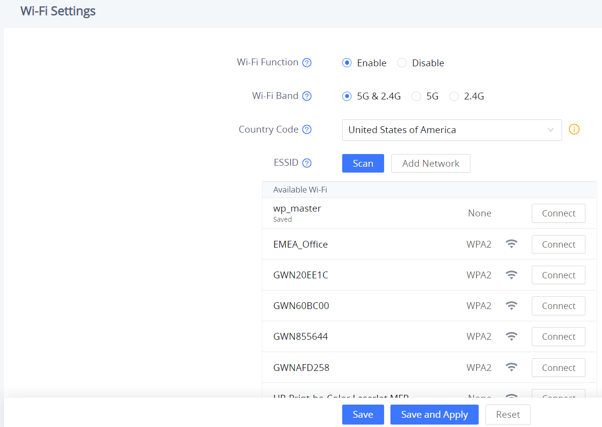
4 – Identify the Wi-Fi network’s SSID and click on “Connect”, then enter the correct password information to connect to the selected network:
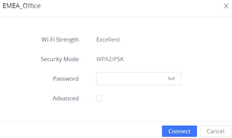
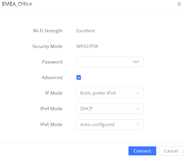
5. Users can check the Wi-Fi parameters and change the setting by checking the “advanced” at the bottom.
Wi-Fi Function | Enables/disables the Wi-Fi feature. The default setting is "Disable". |
Wi-Fi Band | Configures the Wi-Fi frequency band from the dropdown list:
|
Country Code | Configures Wi-Fi country code. The default value is "United States of America". Note: Reboot is requested to take effect. |
ESSID | This parameter sets the ESSID for the Wireless network. Press "Scan" to scan for the available wireless network. |
Scan | Allows to scan and select the available Wi-Fi networks within the range where the Wi-Fi feature is enabled. Click on "Connect" to select the Wi-Fi network and connect. The ESSID will be auto-filled in the ESSID field, users can also click on “Details” to have more details about the connected ESSID with its status, strength, and security mode. they can either edit the attributes of the network or forget the network. |
Add Network | |
ESSID | Determines the ESSID of the default Wi-Fi network. |
Security Mode | This parameter defines the security mode used for the wireless network when the SSID is hidden. 5 Modes are available:
It is set to "None" By default. |
Advanced | When this option is checked, it gives you the possibility to define the following parameters :
|
Password | When the following security modes are picked: Auto, WEP, WPA, and WPA-802.1x, the user must enter a specific password for the ESSID. |
EAP Method | When WPA-802.1x is selected, users can choose one of the below EAP methods which can be configured for credential-based or certificate authentication.
|
Phase 2 Authentication | Configures the keys to encrypt and decrypt the IPSec packets on the host, it can be set to :
|
CA Certificate | Upload the 802.1x CA certificate to the phone, or delete existed 802.1x CA certificate from the phone. |
Anonymous Identity | If an anonymous identity username is entered, the wi-fi connection will use a dummy, anonymous identity to establish the connection. |
Identity | Defines the Identity information for the 802.1x mode. |
Bluetooth
Bluetooth | Enable or Disable Bluetooth |
| Discoverable to Nearby Bluetooth Devices | Enable to be discoverable via Bluetooth by nearby devices. |
Visibility timeout | Configures visibility timeout to nearby devices before turning back to invisible mode. The default is 2 minutes. |
Set up a 6 digits PIN Code. The PIN is required when pairing other Bluetooth devices. | |
Configures the name that will be shown to other Bluetooth devices. | |
Paired devices | Lists paired devices.
Press
|
OpenVPN® Settings
OpenVPN® Enable | Enable/Disable the OpenVPN® feature. Defaut setting is "Disabled" |
Manual Import | |
Import OpenVPN® Configuration | Import the configuration file from the current computer. After importing, the local configuration will be overwritten and OpenVPN® function is automatically enabled. Note: Please import *.ovpn file |
Local Configuration | |
OpenVPN® Server Address | The URL/IP address for the OpenVPN® server. |
OpenVPN® Port | The network port for the OpenVPN® server. By default, it is set to 1194. |
OpenVPN® Transport | Determines network protocol used for OpenVPN®: UDP or TCP. |
OpenVPN® CA | OpenVPN® CA file (ca.crt) required by the OpenVPN® server for authentication purposes. Press “Upload” to upload the corresponding file to the device. |
OpenVPN® Certificate | OpenVPN® Client certificate file (*.crt) required by the OpenVPN® server for authentication purposes. Press “Upload” to upload the corresponding file to the device. |
OpenVPN® Client Key | The OpenVPN® Client key (*.key) required by the OpenVPN® server for authentication purposes. Press “Upload” to upload the corresponding file to the device. |
OpenVPN® TLS Key | Click the button "Upload" to upload TLS key: Note: .key file |
OpenVPN® TLS Key Type | Select the encryption type of the OpenVPN® TLS key. |
OpenVPN® Cipher Method | Same cipher method must be used by the OpenVPN® server: Blowfish, AES=128, AES-256, Triple-DES |
OpenVPN® Username | OpenVPN® authentication username (optional). |
OpenVPN® Password | OpenVPN® authentication password (optional). |
OpenVPN® Comp-lzo | Configures enable/disable the LZO compression. When the LZO Compression is enabled on the OpenVPN server, you must turn on it at the same time. Otherwise, the network will be abnormal. Default value is YES. |
Additional Options | Additional options to be appended to the OpenVPN® config file. Note: Additional options are seperated by semicolon. For example: Please use with caution. |
OpenVPN® Settings
Advanced Settings
| Advanced Network Settings | |
DNS Refresh Timer (m) | Configures the refresh time (in minutes) for DNS query. If set to “0”, the phone will use the DNS query TTL from the DNS server response. |
Configures the duration (in minutes) of the previous DNS cache when theDNS query fails. If set to “0”, the feature will be disabled. Note: Only valid for SIP registration. | |
Enable LLDP | Enables the LLDP (Link Layer Discovery Protocol) feature on the device. If it is set to “Yes”, the device will broadcast LLDP PDU to advertise its identity and capabilities and receive the same from physical adjacent layer 2 peers. The default setting is “Yes”. |
LLDP TX Interval (s) | Configures the interval the device sends LLDP-MED packet. The default setting is 60s. Note: Reboot the device to make changes take effect. |
Enable CDP | Configures whether to enable CDP to receive and/or transmit information from/to CDP-enabled devices. The default setting is “No”. |
Layer 3 QoS for SIP | Defines the Layer 3 packet’s QoS parameter for SIP messages in a decimal pattern. This value is used for IP Precedence, Diff-Serv, or MPLS. The default setting is 26 which is equivalent to the DSCP name constant CS6. |
| Layer 3 QoS for RTP | Defines the Layer 3 packet’s QoS parameter for RTP messages in a decimal pattern. This value is used for IP Precedence, Diff-Serv or MPLS. The default setting is 46 which is equivalent to the DSCP name constant CS6. |
HTTP/HTTPS User-Agent | Sets the user-agent for contacts. Note: Reboot the device to make changes take effect. |
SIP User-Agent | Sets the user-agent for SIP. Default is:
|
Proxy | |
HTTP Proxy | Specifies the HTTP proxy URL for the phone to send packets to. The proxy server will act as an intermediary to route the packets to the destination |
HTTPS Proxy | Specifies the HTTPS proxy URL for the phone to send packets to. The proxy server will act as an intermediary to route the packets to the destination. |
Bypass Proxy For | Defines the destination IP address where no proxy server is needed. The device will not use a proxy server when sending packets to the specified destination IP address. |
System Settings Page Definitions
Time Settings
NTP Server | Configures the URL or IP address of the NTP server. The phone may obtain the date and time from the server. |
Enable Authenticated NTP | Configures whether to enable NTP authentication. If enabled, a cryptographic signature appended to each network packet. If the key is incorrectly configured, the phone will refuse to use the time provided by the NTP server. Default is Disabled |
Allow DHCP Option 42 to Override NTP Server | When enabled, DHCP Option 42 will override the NTP server if it is set up on the LAN. Default is Enableld |
DHCP Option 2 to Override Time Zone Setting | Allows device to get provisioned for Time Zone from DHCP Option 2 in the local server automatically. Default is Enabled |
Time Zone | Specifies the local time zone for the phone. It covers the global time zones and user can selected the specific one from the drop-down list. |
Date Display Format | Determines which format will be used to display the date. It can be selected from the drop-down list:
The default setting is YYYY-MM-DD |
Time Display Format | Specifies which format will be used to display the time. It can be selected from 12-hour and 24-hour format. |
Time Settings
Security Settings
Web/SSH Access | |
Enable SSH | Enables/disables SSH access to the device. The default setting is “Yes”. |
SSH Port | Customizes the SSH port. By default, SSH uses port 22. |
HTTP Web Port | Configures the HTTP port under the HTTP web access mode. |
HTTPS Web Port | Configures the HTTPS port under the HTTPS web access mode. |
Enable User Web Access | The administrator can disable or enable user web access. |
Web Access Mode | Sets the protocol for the web interface.
Default is "Both HTTP and HTTPS" |
User Login Timeout | Configures login timeout (in minutes) for the user. If there is no activity within the specified time, the |
Validate Server Certificates | Configures whether to validate the server certificate when downloading the firmware/config file. If set to "Yes", the phone will download the firmware/config file only after the server is validated. |
User Info Management | |
User Password | |
New Password | Set new password for web GUI access as User. This field is case sensitive. |
Confirm Password | Enter the new User password again to confirm. |
Admin Password | |
Current Password | The current admin password is required to set a new admin password. |
New Password | Set new password for web GUI access as Admin. This field is case sensitive. |
Confirm Password | Enter the new Admin password again to confirm. |
Client Certificate | |
Minimum TLS Version | Specifies the minimum TLS version allowed for the connection. Default is TLS 1.0 |
Maximum TLS Version | Specifies the maximum TLS version allowed for the connection. Default is Unlimited |
Enable Weak TLS Cipher Suites | Defines the function for weak TLS cipher suites:
Default is "Enable Weak TLS Cipher Suites" |
SIP TLS Certificate | The Cert File for the phone to connect to SIP Server via TLS. |
SIP TLS Private Key | The Cert Key for the phone to connect to SIP Server via TLS. |
SIP TLS Private Key Password | SSL Private key password used for SIP Transport in TLS/TCP. |
Custom Certificate | Click on "Upload" to upload a custom certificate. The uploaded custom certificate will be used for SSL/TLS communication instead of the phone default certificate. |
Trusted CA Certificates | |
Upload/Delete | Click on "Upload" to upload a certificate from our computer or click "Delete" to delete the selected certificate |
Load CA Certificates | Phone will verify the server certificate based on the built-in, custom or both trusted certificates list. |
Security Settings
Preferences
LED Management | |
Enable Missed Call Indicator | If enabled, the LED indicator on the upper right corner of the phone will light up when there is missed call on the phone. |
Call Light | Select the LED prompt light during the call. The default light is green. |
Volume Settings | |
Call Volume | Move the slider to configure call volume |
Ringtone Volume | Move the slider to configure ringtone volume |
Media Volume | Move the slider to configure media volume |
Volume Compensation | If enabled, the volume will be automatically adjusted within an appropriate range according to the ambient noise. |
Preferences
TR-069
Enable TR-069 | Sets the device to enable the “CPE WAN Management Protocol” (TR-069). The default setting is “No”. Note: Reboot the device to make changes take effect. |
ACS URL | Specifies URL of TR-069 ACS (e.g, http://acs.test.com), or IP address. |
ACS Username | Enters username to authenticate to ACS. |
ACS Password | Enters password to authenticate to ACS. |
Periodic Inform Enable | Sends periodic inform packets to ACS. The default is “No”. |
Periodic Inform Interval (s) | Configures to send periodic “Inform” packets to ACS based on aspecified intervals. The default setting is 86400. |
Connection Request Username | Enters username for the ACS to connect to the device. |
Connection Request Password | Enters the password for the ACS to connect to the device. |
Connection Request Port | Enters the port for the ACS to connect to the device. |
CPE Cert File | Uploads Cert File for the device to connect to the ACS via SSL. |
CPE Cert Key | Uploads Cert Key for the device to connect to the ACS via SSL. |
Sensor Settings
Basic Settings | |
Basic Settings | |
Sensor Type | Set the initial state of the sensor, when the selection is normally open, the contact is disconnected when static; When the selection is normally closed, the contact is connected when static. The normally open will be connected when the electrical action is on the switch, and the normally closed will disconnected. The default is normally open. |
Trigger Type | Set the type of the trigger mode, and when the selection is level triggered, only high level (1) or low level (0) will trigger the notification. When the edge trigger is selected, the notification is triggered only when the level changes (high level to low level, or low level to high level). The default is level trigger. |
Trigger time | |
Cycle Time | The alarm can be configured to be triggered all days of the week, in this case “All days” option needs to be checked. Or to some specific schedule, in this case “Period of Time” option needs to be checked for users to be able to configure Time and Frequency options below. |
Time | Set the activation time, up to 3 times. When the activation time is not set, the default time is full day. |
Frequency | Set the activation frequency from Monday to Sunday, which can be selected from the whole week. The default value is not selected. |
Play Audio | Play a sound when the switch is triggered during the scheduled time. |
Prompt Tone | When the “voice prompt” is selected, you can upload the customized audio by clicking on “Upload” and choose the file. |
Make Call | Dial the number when the sensor is activated. |
Dial out extension | Enter the number you need to dial and click the “add” button to set two numbers at the same time. |
Hang up | Hang up calls when the sensor is triggered, such as SIP call, multicast, etc. When checked at the same time as Make Call, if there is currently a call, the first trigger will hang up the call, and the second trigger will dial. |
Sensor Settings
Alarm in Settings
Trigger time | |
Cycle Time | Configures the cycle time. If set to "Daily", it will trigger the function every day. If set to "Period of time", it will trigger the function according to the set time period. The default value is "Daily". |
Time | Set the activation time, up to 3 times. When the activation time is not set, the default time is full day. |
Frequency | Set the activation frequency from Monday to Sunday, which can be selected from the whole week. The default value is not selected. |
Play Audio | Play a sound when the switch is triggered during the scheduled time. |
Prompt Tone | When the “voice prompt” is selected, you can upload the customized audio by clicking on “Upload” and choose the file. |
Make Call | Dial the number when the sensor is activated. |
Dial out extension | Enter the number you need to dial and click the “add” button to set two numbers at the same time. |
Alarm in settings
Backup/Restore
The Backup/Restore page is used to back up data or import backup files to restore data. Users can start the Backup by clicking on “Backup”.
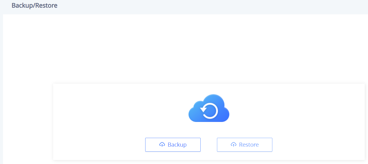
Maintenance Page Definitions
Upgrade and Provisioning
Upgrade and Provisioning/Firmware
Upgrade via Manually Upload | |
Upload Firmware File to Update | Allows users to load the local firmware to the device to update the firmware. |
Upgrade via Network | |
Firmware Upgrade via | Configures firmware upgrade method as TFTP, HTTP, HTTPS, FTP or FTPS. Default is HTTP |
Firmware Server Path | Sets IP address or domain name of firmware server. The URL of the server that hosts the firmware release. Default is “fm.grandstream.com/gs”. |
Firmware Server Username | The username for the firmware server. |
Firmware Server Password | The password for the firmware server. |
Firmware File Prefix | Checks if firmware file is with matching prefix before downloading it. This field enables user to store different versions of firmware files in one directory on the firmware server. |
Firmware File Postfix | Checks if firmware file is with matching postfix before downloading it. This field enables user to store different versions of firmware files in one directory on the firmware server. |
Upgrade Detection | |
Upgrade | Click the “Start” button to check whether the firmware in the firmware server has an updated version, if so, update immediately. |
Upgrade and Provisioning – Firmware page
Upgrade and Provisioning/Config File
Configure Manually | |
Download Device Configuration | Click to download the device configuration file in .txt format. |
Upload Device Configuration | Upload config file to the phone. |
Configure via Network | |
Config Upgrade via | Configures the config upgrade method as TFTP, HTTP, HTTPS, FTP or FTPS. Default is HTTPS |
Config Server Path | Sets IP address or domain name of configuration server. The server hosts a copy of the configuration file to be installed on the device. Default is “fm.grandstream.com/gs”. |
Config Server Username | The username for the config server. |
Config Server Password | The password for the config server. |
Config File Prefix | Checks if configuration files are with matching prefix before downloading them. This field enables user to store different configuration files in one directory on the provisioning server. |
Config File Postfix | Checks if configuration files are with matching postfix before downloading them. This field enables user to store different configuration files in one directory on the provisioning server. |
Authenticate Conf File | Sets the device to authenticate configuration file before applying it. When set to “Yes”, the configuration file must include value P1 with phone system’s administration password. If it is missed or does not match the password, the device will not apply it. Default setting is “No”. |
XML Config File Password | Decrypts XML configuration file when encrypted. The password used for encrypting the XML configuration file is using OpenSSL. |
Upgrade and Provisioning – Config File page
Upgrade and Provisioning/Provision
Auto Upgrade | |
Automatic Upgrade | Specifies when the firmware upgrade process will be initiated; there are 4 options:
Note: Day of week is starting from Sunday. The default setting is “No”. |
Start Upgrade at Random Time | Configures whether the phone will upgrade automatically at a random time within the configured time interval. |
Firmware Upgrade and Provisioning | Defines the device’s rules for automatic upgrade. It can be selected from:
The default setting is “Always Check for new firmware”. |
DHCP Option | |
Allow DHCP Option 43 and Option 66 to Override Server |
The default setting is “Yes”. |
Allow DHCP Option 120 to Override SIP Server | Configures the device to allow the DHCP offer message to override the Config Server Path via the Option 120 header. The default setting is "Disabled". |
Additional Override DHCP Option | Configures additional DHCP Option to be used for firmware server instead of the configured firmware server or the server from DHCP Option 43 and 66. This option will be effective only when "Allow DHCP Option 43 and Option 66 to Override Server" is enabled. There are 3 options:
The default setting is "Option 150" |
Allow DHCP Option 242 (Avaya IP Phones) | Enables DHCP Option 242. Once enabled, the device will use the configuration info issued by the local DHCP in Option 242 to configure proxy, transport protocol and server path. The default setting is “Disabled”. |
Config Provision | |
Config Provision | Device will download the configuration files and provision by the configured order. Use arrow buttons to add and order configuration files. |
Download and Process All Available Config Files | By default, the device will provision the first available config in the order of cfgMAC, cfgMAC.xml, cfgMODEL.xml, and cfg.xml (corresponding to device specific, model specific, and global configs). If set to “Yes”, the device will download and apply (override) all available configs in the order of cfgMAC, cfg.xml, cfgMODEL.xml, cfgMAC.xml. |
3CX Auto Provision | If enabled, the phone will send SUBSCRIBE requests to the multicast address in LAN during bootup for automatic provisioning. This feature requires 3CX server support. Default setting is "Enabled". |
Upgrade and Provisioning – Provision page
Upgrade and Provisioning/Advanced Settings
Send HTTP Basic Authentication By Default | Determine whether to send basic HTTP authentication information to the server by default when using wget to download firmware or config file. If set to "Yes", send HTTP/HTTPS user name and password no matter the server needs authentication or not. If set to "No", only send HTTP/HTTPS user name and password when the server needs authentication. The default value is “Disabled”. |
Enable SIP NOTIFY Authentication | Device will challenge NOTIFY with 401 when set to "Yes". The default value is “Enabled”. |
Validate Hostname in Certificate | Configures to validate the hostname in the SSL certificate. The default value is “Disabled”. |
Allow AutoConfig Service Access | Set to allow access to the AutoConfig service. If not checked, access to service.ipvideotalk.com will be disabled. The default value is “Enabled”. |
Factory Reset | Resets the device to the default factory setting mode by clicking on "Start button". |
Upgrade and Provisioning – Advanced Settings page
System Diagnosis
Syslog | |
Syslog Protocol | Select the transport protocol over which log messages will be carried.
|
Syslog Server | The URL/IP address for the syslog server. |
Syslog Level | Selects the level of logging for syslog. There are 4 levels from the dropdown list: DEBUG, INFO, WARNING and ERROR. The following information will be included in the syslog packet:
Note: Changing syslog level does not require a reboot to take effect. The default setting is “None”. |
Syslog Keyword Filter | Only send the syslog with keyword, multiple keywords are separated by comma. Example: set the filter keyword to “SIP” to filter SIP log. |
Send SIP Log | Configures whether the SIP log will be included in the syslog messages. Default is "Disabled" |
Packet Capture | |
With RTP Packets | Configures whether the packet capture file contains RTP or not. Then click "Start" to start Packet Capture or "Stop" to stop the Packet Capture. |
With Secret Key Information | Configures whether the packet capture file contains secret key information or not. Then click "Start" to start Packet Capture or "Stop" to stop the Packet Capture. |
Ping | |
Enter the URL into the textbox then click "Start" to begin the ping, Results will be shown below. | |
Traceroute | |
Enter the URL into the textbox then click "Start" to begin the Traceroute, Results will be shown below. | |
Remote Diagnostics | |
When enabled, this device will allow remote access and remote collection of logs. It will automatically end when it expires. Note: Click on "Start", then the Access Address and Expiration Time will be shown below. | |
System Diagnostics page
Event Notification
Set the URL for events on the phone web GUI, and when the corresponding event occurs on the device, the device will send the configured URL to the SIP server. The dynamic variables in the URL will be replaced by the actual values of the device before sending it to the SIP server, in order to achieve the purpose of events notification. Here are the standards:
- The IP address of the SIP server needs to be added at the beginning and separate the dynamic variables with a “/”.
- The dynamic variables need to have a “$” at the beginning. For example: local=$local
- If users need to add multiple dynamic variables in the same event, users could use “&” to connect with different dynamic variables. For example: 192.168.40.207/mac=$mac&local=$local
- When the corresponding event occurs on the device, the device will send the MAC address and phone number to the server address 192.168.40.207.
Phone Status | |
Bootup Completed | Configures the event URL when phone boots up. |
Registered | Configures the event URL when an account in the device is registered successfully. |
Unregistered | Configures the event URL when an account in the device is unregistered. |
Call Operation | |
Incoming Call | Configures the event URL when phone has an incoming call. |
Outgoing Call | Configures the event URL when phone has an outgoing call. |
Missed Call | Configures the event URL when the device has new a missed call. |
Established Call | Configures the event URL when a call is established. |
Terminated Call | Configures the Action URL to send when phone terminates a call. |
Log On | Configures the event URL when users log on the device successfully. |
Log Off | Configures the event URL when users log off the device. |
Event Notification
Application Page Definitions
Music
Playback | |
Audio File | Please select the audio file type:
|
RTSP stream address | Supports RTSP stream address to obtain audio Ex : (rtsp://[IP]:[port]/[audio file name]), supporting MP3 and TS formats. |
Local Music | Displays the audio tracks uploaded to the cloud. It Supports .mp3 and .ogg audio formats only. |
Share Music | Prompts a popup browser tab or window from which the music will be streamed, play music on PC first, and click to select the music window to be shared to the GSC. It is recommended to use the browser Chrome (72 and above), Edge (79 and above), Otherwise it may be silent after sharing. |
Timed playback Click on "Add rule" to create Timed playback rule | |
Timed playback rule | |
Audio File | Please select the audio file type |
RTSP stream address / Local Music | If RTSP stream is selected: Support RTSP stream address to obtain audio(rtsp://[IP]:[port]/[audio file name]), supporting MP3 and TS formats. If Local Music is selected: Please select local music, supporting MP3 and OGG formats. |
Play Mode |
|
Play interval (s) | Configure the interval between the two playbacks. the valid range is 0-1800 seconds. |
Play Time | Set the trigger time, up to 3 items can be set. Click on "+" to add more |
Frequency | Configures the activation frequency from Monday to Sunday. Up to 7 days can be selected. Default value is not selected. |
Music
Playback Cascade
Playback Cascade | |
Cascade role Select the cascade role. Only cascading on the same network segment is supported and only one Master is allowed. You can set the cascade role to either "Slave", "Master", or "None", By Default, it is set to "Slave". | |
Multicast Address | In the case of a Master Cascade role, Enter the multicast address and port. As the Master, multicast will be initiated by this address. As the Slave, it will automatically obtain the address initiated by the Master. |
Forwarding Category | This options selects the type of audio to forward. it can be Music Media , call or alarm. |
Trigger Time Gives the option to add a triggering time for the Playback | |
Playback time | Configures the activation time. Up to 3 entries can be configured. When the activation time is not set, the default time is a full day. |
Frequency | Configures the activation frequency from Monday to Sunday. Up to 7 days can be selected. The default value is not selected. |
Playback Cascade
GSC Assistant
GSC Assistant | |
Managed by GSC Assistant App | Configures the ability for the device to be detectable by the GSC Assistant App. |
Device Label | Defines under what label the GSC shows up during the scan. |
Diagnostic Page Definitions
Audio Loop Test
An audio loop test is used to test the MICs. Each one of the MICs is tested separately.
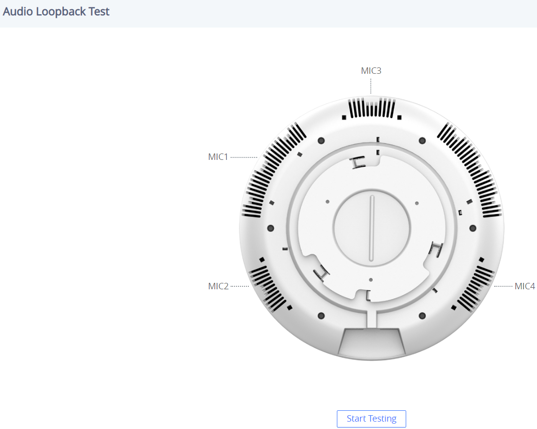
Built-in Speaker Test
Built-in Speaker Test is used to test the devices by playing a piece of music in order to verify the sound quality.

Volume Key Test
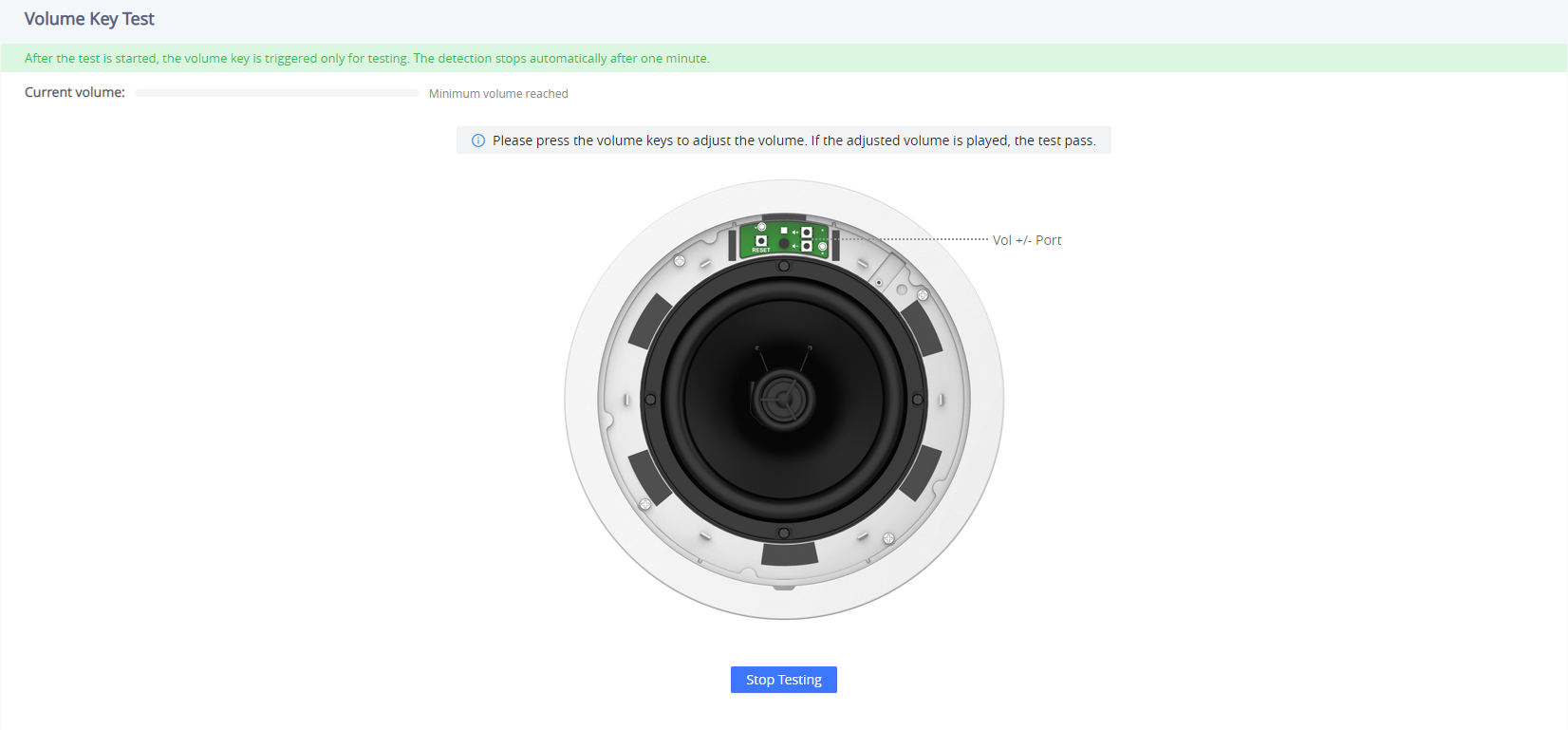
LED Test
The LED Test is used to test the availability of the four colored LEDs and their intensity. The colors of LEDs available are Green, Red, Blue, and White.
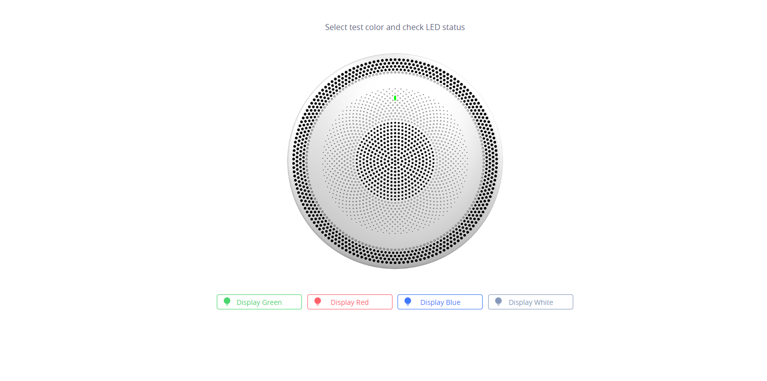
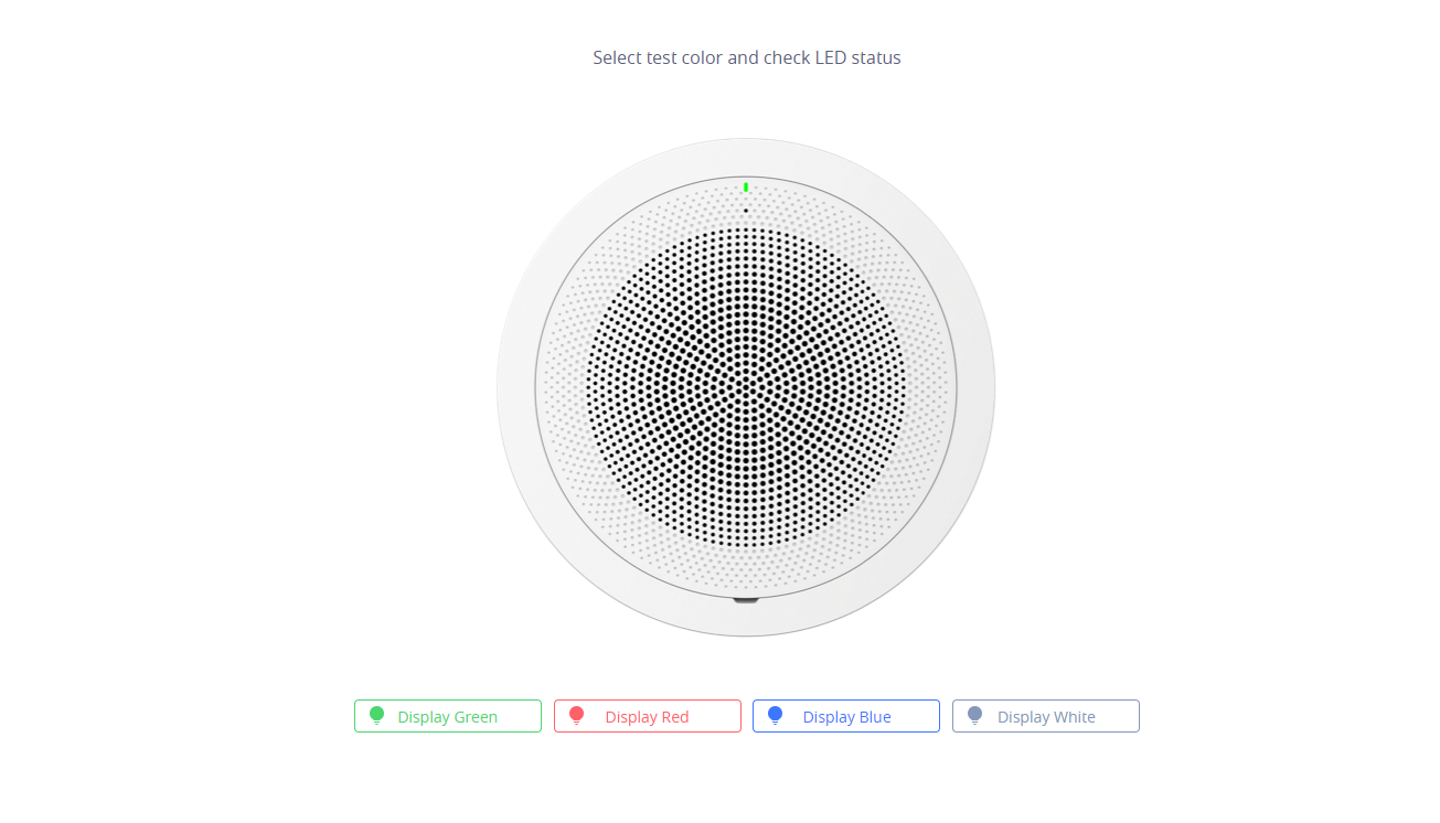
Certificate Verify
Certificate Verify is used to test the validity of the existing certificate.
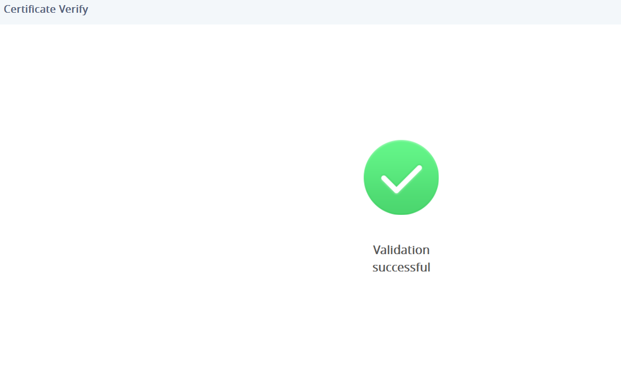
Reset Button Test
Reset Button Test is used to test the Reset button, during the test the reset button doesn’t trigger a factory reset, this feature allows the user to check if the button is responding.
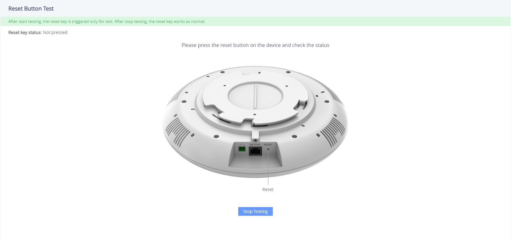
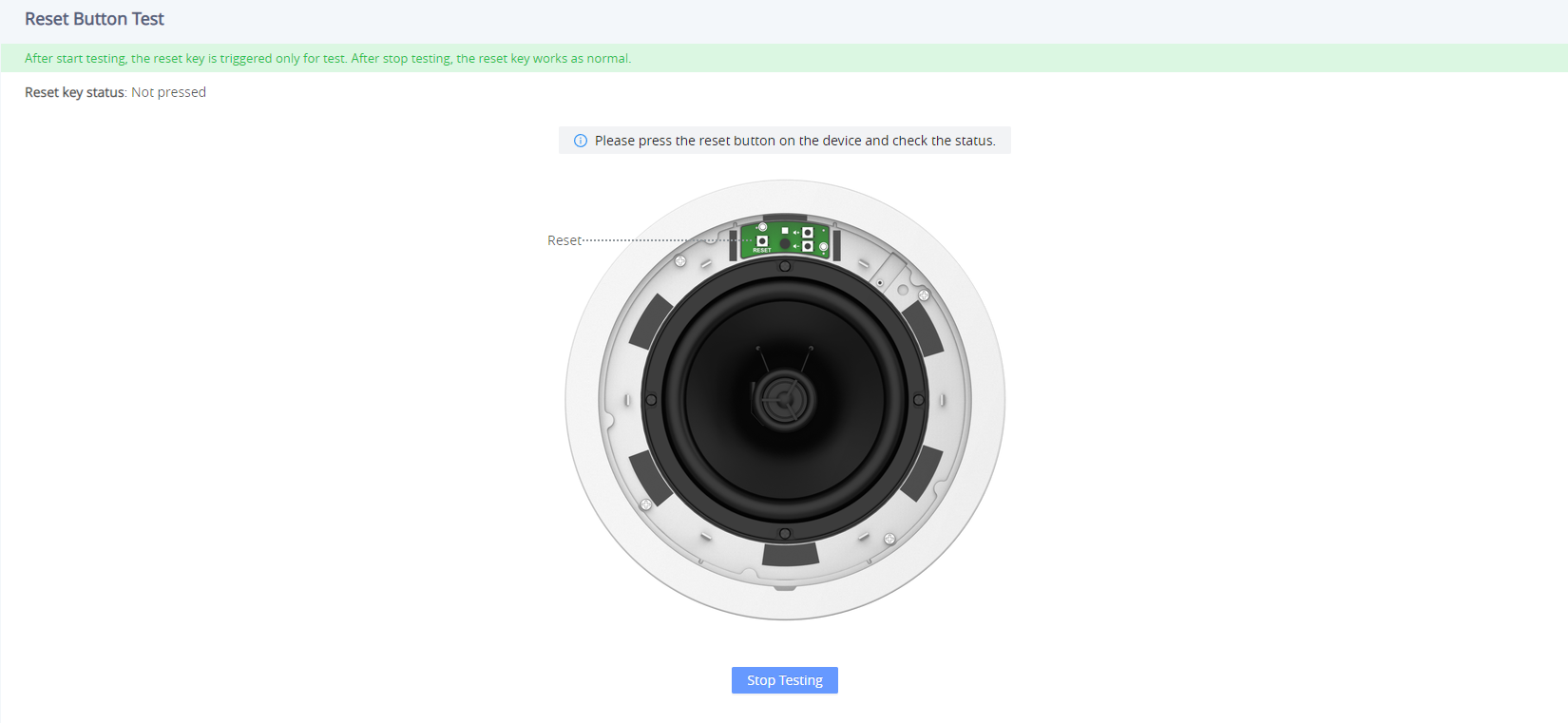
Sensor Detection
Click on “Start Testing” ![]() to start the testing for the 2-PIN Port.
to start the testing for the 2-PIN Port.
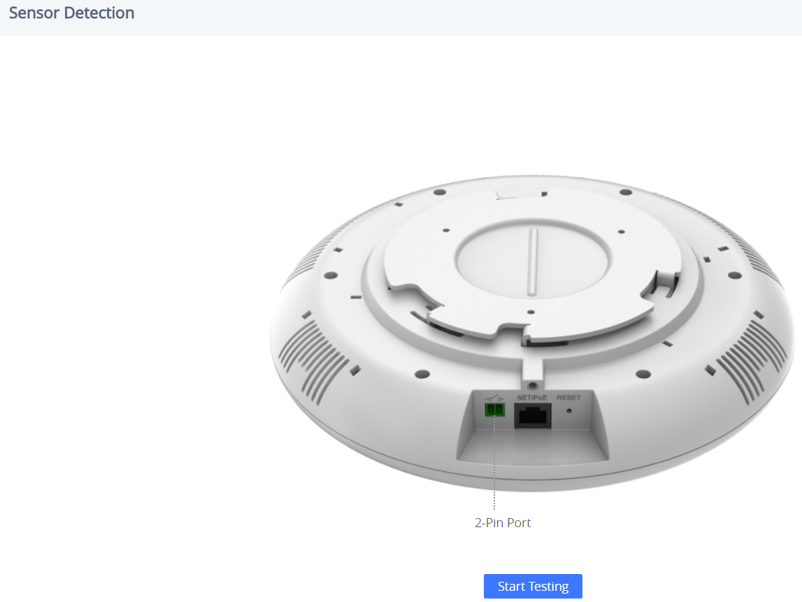
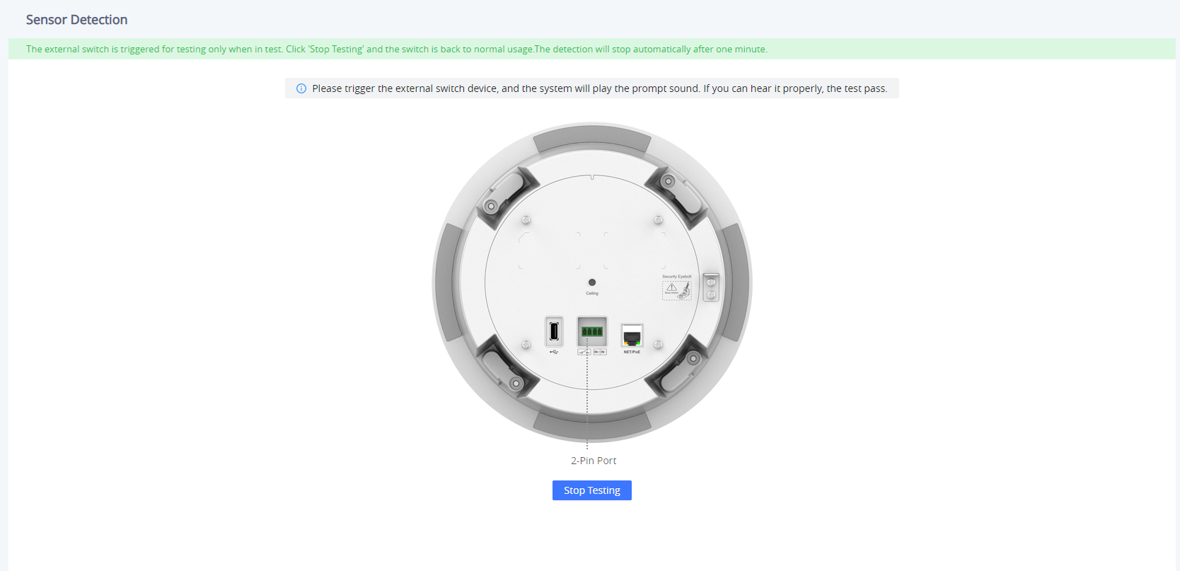
Alarm in Test
Click on “Start Testing” ![]() to start the testing for the Alarm in test.
to start the testing for the Alarm in test.
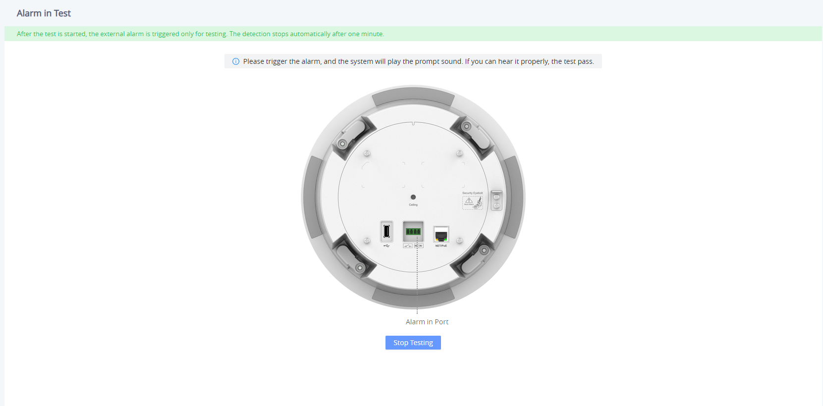
USB Test
Click on “Start Testing” ![]() to start the testing for the USB Test.
to start the testing for the USB Test.
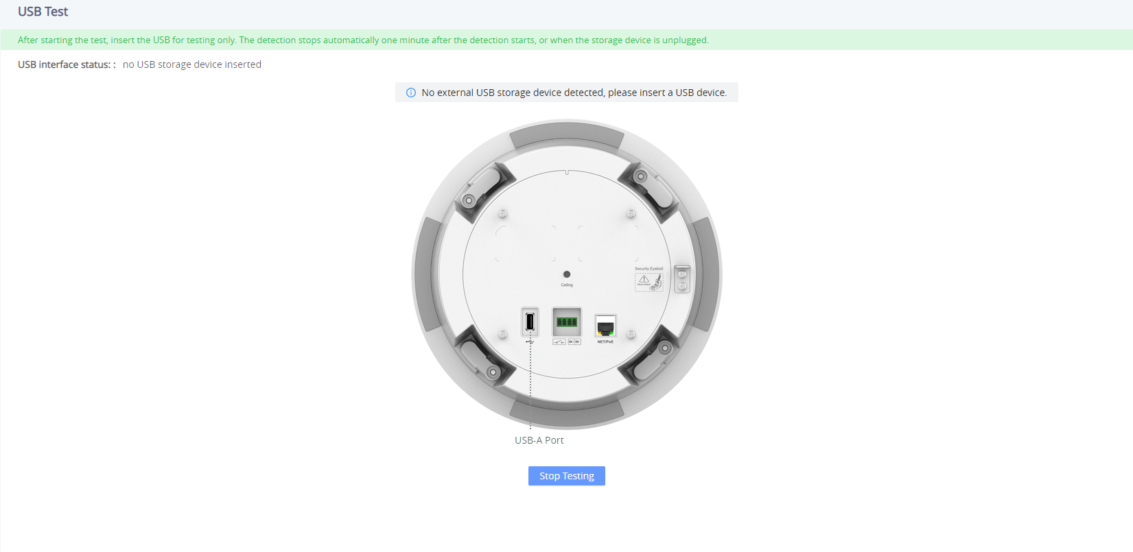
Factory Reset
To perform a factory reset via the Web GUI, Navigate to Diagnostic → Factory Reset, click on the “Factory Reset” button then click on “OK” to confirm the factory reset.

EXPERIENCING THE GSC35X6
Please visit our website: https://www.grandstream.com to receive the most up-to-date updates on firmware releases, additional features, FAQs, documentation, and news on new products.
We encourage you to browse our product-related documentation, FAQs, and User and Developer Forum for answers to your general questions. If you have purchased our products through a Grandstream Certified Partner or Reseller, please contact them directly for immediate support.
Our technical support staff is trained and ready to answer all of your questions. Contact a technical support member or submit a trouble ticket online to receive in-depth support.
Thank you again for purchasing Grandstream SIP Speaker, it will be sure to bring convenience and color to both your business and personal life.
CHANGE LOG
This section documents significant changes from previous versions of the user manual for the GSC35XX Series. Only major new features or major document updates are listed here. Minor updates for corrections or editing are not documented here.
Firmware Version 1.0.5.8
Product name: GSC3506, GSC3516
- Added ability to enable/disable “User” web access. [ENABLE USER WEB ACCESS]
- Disabled the “User” Web UI account by default. [ENABLE USER WEB ACCESS]
- Added a prompt to change password when logging in to account “User” for the first time [Enable User Web Access]
Firmware Version 1.0.5.7
Product name: GSC3506, GSC3516
- Added ability to disable start and end of multicast tones. [Multicast Tone] [End-Call Tone]
- Added ability to change the LED color for calls during an active call. [Call Light]
Firmware Version 1.0.5.4
Product name: GSC3506, GSC3516
- Added pvalue support on the alias template to support UCM Zero Config custom parameters. [Download Device Configuration]
- Added support for RTP timeout. [RIP TIMEOUT]
- Added the ability to change the web login timeout value. [WEB LOGIN TIMEOUT]
Firmware Version 1.0.3.8
Product name: GSC3506, GSC3516
- Added support for GSC Assistant. [GSC ASSISTANT]
Firmware Version 1.0.3.4
Product name: GSC3506, GSC3516
- Remove the start and end of multicast tones. [Multicast]
Firmware Version 1.0.1.29
Product name: GSC3516
- This is the initial version.
Firmware Version 1.0.1.13
Product name: GSC3506
- This is the initial version.