
INTRODUCTION
In this guide we will cover the integration of GSC361x Full HD IP camera with the GSC3570 intercom and facility control station in a doorbell and OpenDoor scenario.
The GSC3570 intercom and facility control station can be used as a digital doorbell and door opener when the door strike is wired directly to the GSC3570.
This scenario can be used alongside GSC361x IP cameras for video monitoring of doors when performing the remote OpenDoor function from GSC3570.
CONNECTION & WIRING DIAGRAM
Below diagram is representing the wiring needed for GSC3570 to be used as a digital doorbell and / or a door opener.
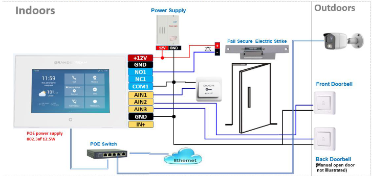
Notes:
GSC3570 AS A DIGITAL DOORBELL & DOOR OPENER
The GSC3570 can behave like a doorbell and door opener if the door strike is wired directly to the relay control port of GSC3570. Refer to the previous section CONNECTION & WIRING DIAGRAM for further details about the connection and wiring needed.
This is a perfect digital upgrade solution for users with broken traditional analog doorbell system. The existing wiring and switch can be connected to GSC3570 so visitors pressing the door switch the GSC3570 will play DING-DONG doorbell tone. If connecting the electrical strike directly to the GSC3570 relay control port, then user can press the Open-door softkey icon on the GSC3570 to open door directly.
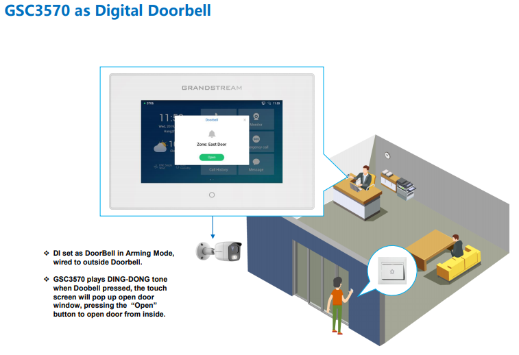
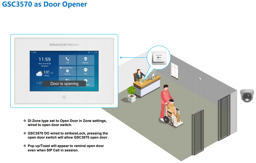
Example Use Cases
The figures below illustrate use case examples for Digital Doorbell and Open Door using GSC3570.
GSC3570 Doorbell & Door Open Configuration Settings
The configuration can be done from the GSC3570 LCD touch screen by following the 3 steps as described below:
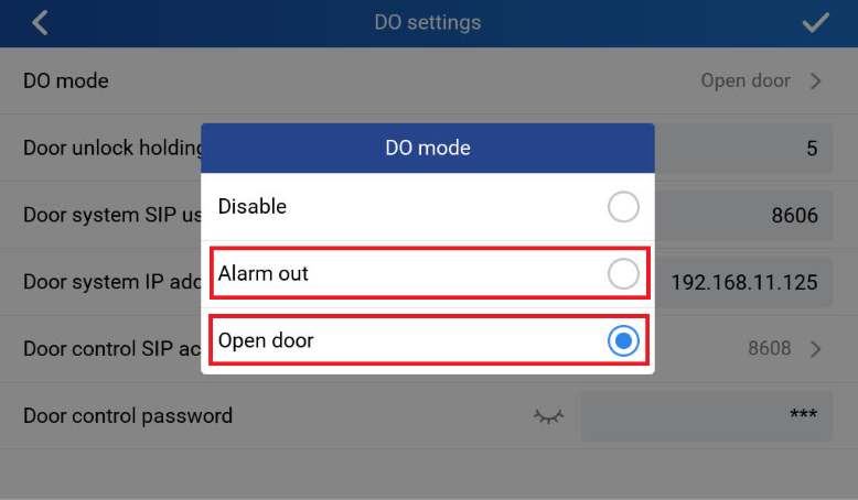
I. “DO mode” set to “Alarm out” OR “Open door”:
- Press “Settings” on the touch panel and go to “DO settings”
- Choose “DO mode”, select “Alarm out” if no door strike connected and only want to use the Ding-Dong doorbell tone. No virtual OpenDoor button will be displayed in Alarm Message.
- Choose “Open door” if COM1, NO1/NC1 are connected to strike to control door opening. Green virtual OpenDoor button when be displayed in Alarm Message when the doorbell switch is pressed.
- Press ✔sign to save the changes.
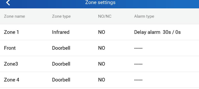
II. Edit Zone settings for Doorbell:
- Press “Settings” on the touch panel.
- Press “Zone settings”, by default there are 4 zones. Only Zone 2, Zone 3 and Zone 4 can be used for Doorbell switch (Zone 1 requires power input).
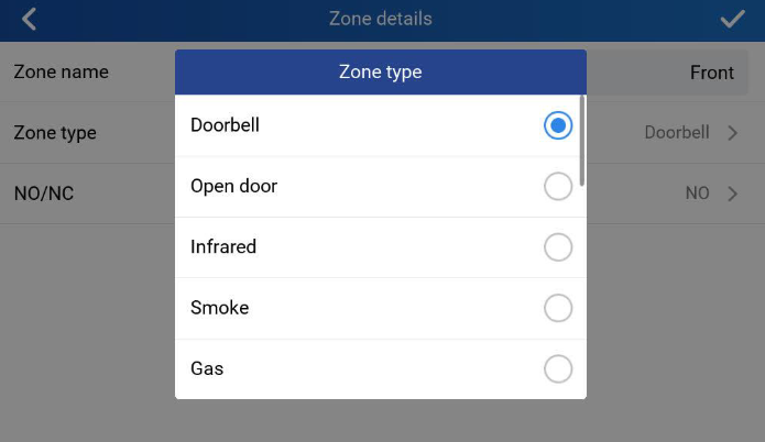
- Press related Zone (2 to 4) to edit. In the screenshot below, Zone 2 name is changed to Front as “Front Door” and “Zone type” is changed to “Doorbell”.
- Press ✔sign to save the changes.
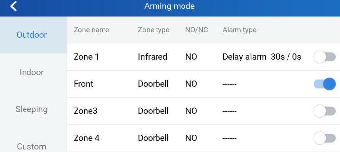
III. Enable the Arming mode to enable the doorbell:
- Press “Arming mode” to enable the change in above Step I.
- Select the Arming mode used. For example, “Outdoor” is selected because the doorbell is located at outside. Swipe the grey button to enable the feature, the button will turn to blue when enabled.
- Press “<” icon to exit the configuration to idle screen.
- The “Arming status” icon will change color (green). To show the device is “Armed”, or the feature is enabled.
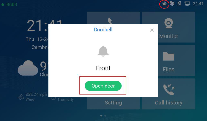
Once configured, and upon pressing the doorbell or switch (AIN1 and GND short-circuit), “DING DONG” doorbell tone will be played at GSC3570, a green open door virtual button will be displayed on the screen (if configured and wired the strike). Press the green “Open door” virtual button, the relay will take reaction to open the door.
The GSC3570 top right corner will also display a door opened icon and an “alarm” icon and “Message” will be displayed with front and back red LED flashing, reminding there is an open door (alarming) event happened. Press the “Messages” icon to check what the message is then exit the UI, the alarm message and the flashing LEDs will disappear.
CONNECTING GSC361X WITH GSC3570 FOR VIDEO MONITOR
In this configuration example we will be using two GSC361x IP cameras and one GSC3570 Control Station.
- The GSC3615 and GSC3570 are both configured with a SIP account under the same SIP server.
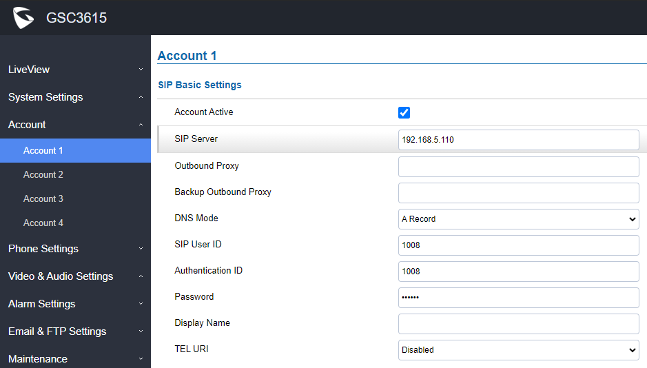
- GSC3615 will be configured with SIP account “1008”
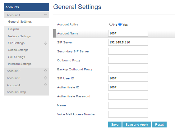
- GSC3570 will be configured with SIP account “1007”
- The SIP server IP in our example is: 192.168.5.110
- The GSC3610 with IP 192.168.5.169 without a registered SIP account and will be used as a second camera for RTSP video streaming.
GSC361x Configuration Settings
SIP Account Settings
We first start with configuring the SIP account from the GSC3615 Web GUI, For this matter, navigate to “Account” 🡪 “Account X” , and set your SIP settings accordingly.
Video Settings
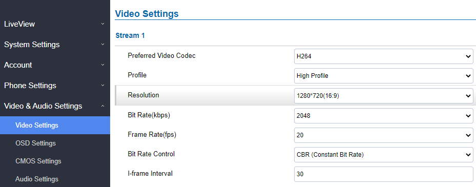
From both GSC361x IP cameras used, we need to set the video stream parameters according to the maximum supported in the GSC3570 control station, namely (Video resolution up to 720p, Frame rate up to 30 fps, Bit rate up to 2Mbps).
To change these settings from the GSC361x Web GUI by navigating to “Video & Audio Settings” 🡪 “Video Settings”, Below screenshot is an example for Stream 1 video settings.
Note:
GSC3570 Configuration Settings
SIP Account Settings
From the GSC3570 Web GUI we navigate to “Accounts” 🡪 “Account X” 🡪 “General Settings” in order to configure the SIP account that will be used for video calls towards the GSC361x IP camera, The below screenshot is an example from our configuration.
Adding GSC361x IP Camera
The GSC3570 can be configured with up to 32 IP camera including GSC361x models.
The configuration can be done from GSC3570 as follow:
- Web GUI configuration:
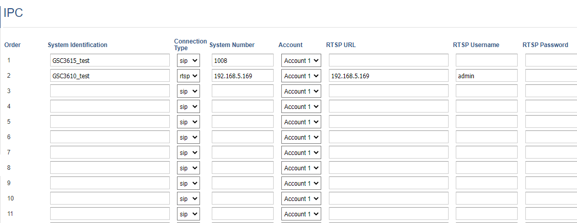
- Access Settings🡪 IPC.
- Enter a name for the IP Camera in System Identification. (not a mandatory field)
- Select SIP or RTSP in Connection Type.
- In System Number enter the GSC361x SIP extension or (IP address in case of peering scenario).
- Select the Account that will be making outgoing calls towards the GSC361x under Account.
- Click on Save and Apply.
Notes:
LCD configuration:
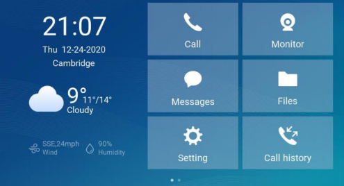
- Tap the menu button if GSC3570 is in idle state.
- On the first screen menu, tap Monitor🡪 IP Camera.
- Press the Add or + button to add a new IP Camera.
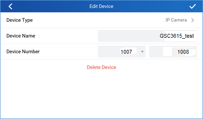
- Enter the GSC361x IP Camera Name in Device Name field.
- Select which Account to make outgoing call towards the GSC361x IP Camera and enter its SIP extension (or IP address in case of peering scenario) in Device Number field.
Video Monitor
Video Monitor by SIP Call
Now that we have configured both, the GSC361x IP camera and GSC3570 control station as shown in the previous sections, The GSC3570 is ready to be used as a video monitoring screen for GSC361x to check who is near the door when GSC3570 receives a Doorbell notification. This can be achieved by initiating a SIP call or using RTSP video streaming.
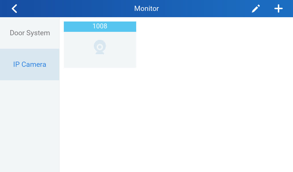
The GSC361x and GSC3570 were previously configured with SIP accounts registered to the same SIP server. Users can initiate SIP video calls from the GSC3570 LCD screen by dialing the SIP extension of the GSC361x IP camera, or otherwise from “Monitor” tab as shown in below screenshot.
And select “IP Camera” , then press the call icon to the account you want to initiate the video call to, in our example “1008”.
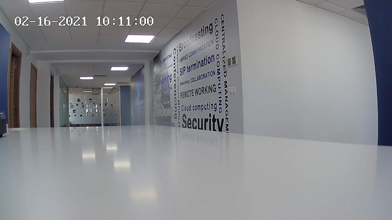
Once the call button pressed, the GSC3570 will initiate a video call to the GSC361x IP camera, and as the auto-answer is enabled by default, the video call is established immediately, and we can see it from the GSC3570 LCD screen like the example from below screenshot.
Video Monitor by RTSP Streaming
The other method to video monitor from the GSC3570 control station is using the RTSP video streaming, in our example as mentioned in the previous sections, we have used a GSC3610 IP camera that we have called “GSC3610_test”.
Once pressing the play icon, the RTSP video streaming will be initiated, and you can check the video feed from the GSC361x IP camera as shown in below screenshot.
SUPPORTED DEVICES
The following table below shows the supported devices:
| Model | Minimum Firmware |
| GSC3610/GSC3615 | 1.0.3.5 or higher |
| GSC3570 | 1.0.5.9 or higher |