
Most enterprise networks are including more and more wireless technologies on their infrastructure and with the well-known WiFi standard for wireless data transmission, DECT technology sits as the most reliable solution for on premises telephony systems which are managed by local PBX. This guide illustrates the steps and recommendations to setup a DECT system using our DP750 base station, DP720 handset and the repeater DP760. Beside DECT and wireless aspects, it also addresses network requirements, capacity planning and measuring methods to ensure good coverage and call quality on customers sites.
Deployment of base stations and repeaters is a central aspect of any DECT phone solution. To successfully deploy the DECT phone system, the deployment concepts, recommendations and methods explained in this guide shall be followed.
GRANDSTREAM IP DECT SOLUTION
About DECT
DECT stands for Digital Enhanced Cordless Telecommunications. DECT is a digital wireless technology which was originated in Europe that’s why earlier DECT used to stands for Digital European Cordless Telecommunication, but is being adopted increasingly worldwide especially America, for cordless telephones. DECT has been especially designed and specified to interwork with many other types of network which allows communication, such as the PSTN (conventional telephone networks), ISDN (new digital and data phone networks), GSM (mobile phone networks) and more. DECT has been developed for short distance communication and large number of user which make them ideal for home cordless phones and small medium size enterprises.
Some DECT Properties:
- Audio codec: G.726.
- Net bit rate: 32 kbit/s.
- Frequency: 1880 MHz–1900 MHz in Europe, 1920 MHz–1930 MHz in the US.
- Carriers: 10 (1,728 kHz spacing) in Europe, 5 (1,728 kHz spacing) in the US.
- Channel allocation: dynamic.
- Average transmission power: 10 mW (250 mW peak) in EU, 4 mW (100 mW peak) in the US.
Advantages of DECT:
- High Subscriber Density.
- 1.8Ghz Frequency Band specially allocated for DECT devices.
- Interference Free Communication.
- Faster and secure communication.
Grandstream IP DECT Solution
Grandstream offers a reliable IP DECT solution based on the combination of DP750/DP752/DP755 base station and DP720 handset along with a powerful DECT repeater DP760 which helps increase the coverage range when needed, the following tables list the major specifications of these devices:
DP750  |
|
DP750 Specifications Overview
DP752  |
|
DP752 Specifications Overview
DP755 |
|
DP755 Specifications Overview
DP760  |
|
DP760 Specifications Overview
For more details, technical specifications and configuration please refer to the following link:
https://www.grandstream.com/products/ip-voice-telephony/dect-cordless
SITE PLANNING AND CONSIDERATIONS
DECT deployment assessment is essential to determine elements necessary to achieve the overall expectations of the user. This includes site survey, determination of type and architecture of the building along with considering interference factors and finally the estimated traffic in the covered area. The following sections will cover in more details most of these considerations.
Wireless Range
The DP75x base station sends the wireless signal in all directions making the wireless coverage in a ring shape.
- Up to 50m indoors.
- Up to 300m outdoors. (For DP750)
Obviously with obstructing objects the range is less than the above values.
Site Survey and Interference Factors
Site survey is the process where a number of requirements and information are collected from the user as well as any conditions that may affect the network and that should be considered during the deployment. Begin the site survey by interviewing the user representative familiar with the full expectation of coverage and performance of IP DECT phone solution. While asking for the following requirements:
- Planned radio coverage area.
- Capacity in terms of the number of users, handsets and connections.
- Known problem areas and what to do about them.
- Any future change on the building.
- Expected traffic behavior (hours of high density).
- Also, it is recommended to request a building plan to help in the planning process.
Another criterion that should be taken into consideration during information gathering is the interference factors, which includes the type of material existing on the coverage area and the potential existence of neighboring wireless signal sources and networks which can affect the performance of the planned DECT telephony system.
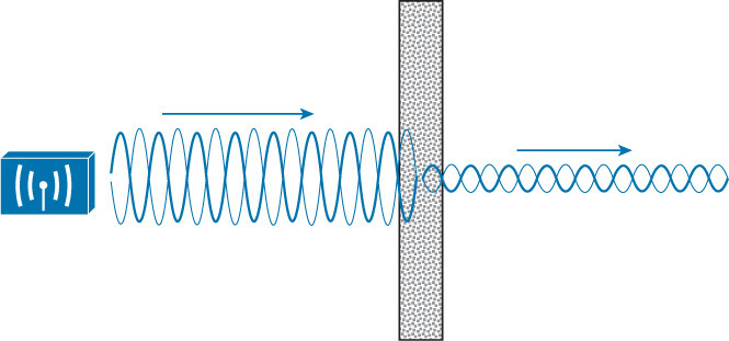
Figure 1: Attenuation Phenomenon
The following table gives some general guidelines on the degree to which certain materials will obstruct the radio signal. Users need also to check if there are neighboring wireless networks operating on the same frequency band.
Table 4: Radio Attenuation for different Materials
Materials | Degree of Attenuation | Example |
Air | None | Open Space |
Wood | Low | Door, floor. |
Plastic | Low | Partition. |
Glass | Low | Un-tinted windows, partition. |
Tinted Glass | Medium | Tinted windows, partition. |
Living Creatures | Medium | Crowds, plants. |
Bricks | Medium | Walls. |
Ceramic | High | Tiles. |
Concrete | High | Walls, floors, pillars. |
Metal | Very High | Metal cabinet. |
Capacity Planning
The following table resumes the number of concurrent calls supported on DP7xx
DP750 base station | 5 calls |
DP760 repeater | 2 calls |
To avoid insufficient user experience through a congested DECT network, the capacity for the DECT network must be large enough to guarantee that the subscribers can be reached in high-density traffic. A cell is at full capacity when the number of connections required for each base station is larger than the number of possible connections. Due to different usage patterns, the number of base stations required to fulfill this demand for voice channels may vary.
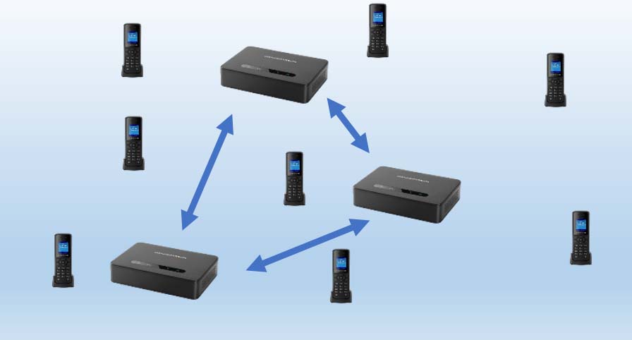
Figure 2: High Traffic Area
DEPLOYMENT GUIDE
This chapter contains the notion of cell coverage and the consideration to be taken when planning the deployment of base stations around the site to achieve better quality.
Using Multiple Base Stations
Cell Coverage
As described before, the cell of a DP75x is ideally in a ring shape. But in real world situations, many obstructions can affect the signal and the coverage doesn’t reach all intended distance. Thus, prior measurements need to be performed in order to guarantee full coverage of the site.
For good coverage, users are recommended to place base stations at appropriate height (around 2m) and near to the center of the site as much as possible while maintaining good signal quality in far critical points.
Single Floor Buildings
When deploying a single floor building, first we recommend that you get an existing building plan to help you have better vision of the site. The process consists of the following steps.
Step 1: Critical points identification
Critical points are dead spots where the radio signal can hardly reach, such as a corner of a room, lifts and stairwells. Please refer to following in order to determine and identify the critical points for placing the deployment base stations.
- Select the first critical point T1 located in the corner area of the site.
- Select a nearby critical point adjacent to the first one and name it T2.
Step 2: Placement of the first base station
- Place the temporary base stations on the critical points.
- Measure the radio coverage and mark the limit of the radio coverage far from the 2 critical points.
- Determine the intersection point of the two temporary coverage cells.
- The intersection point P1 will indicate the best placement for the permanent base station since from this point we can cover the critical points along with neighboring areas.
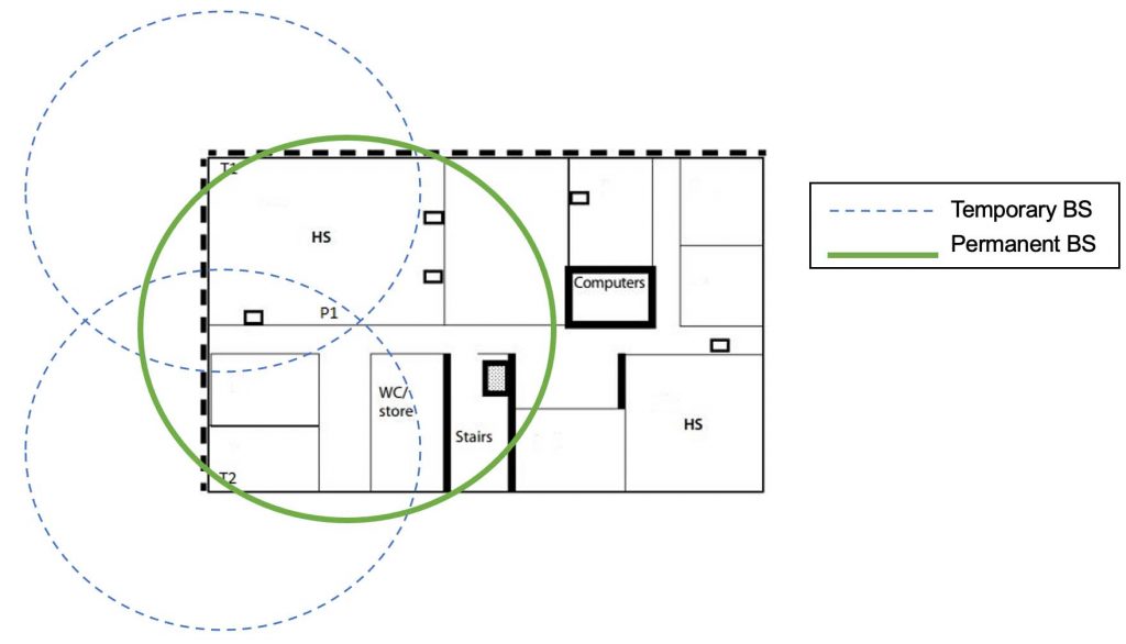
Figure 3: Single Floor Building Deployment
Step 3: Placement of the Next Base Stations
Same procedure can be repeated again to determine best placement for next base station, users can mark critical points on the edge of the site where the signal from first base station is weak, then place temporary base stations in order to set intersection point of their coverage as the position for the next base station.
Areas marked with HS are (hotspots) and multiple base stations can be placed in these areas to provide enough capacity for the subscribers.
Wide Area Scenario
When the cell coverage of the temporary base station doesn’t intersect with each other, users could place first permanent base stations at the edges of the site while trying to have them (in a 45°) near to the center of the site as much as possible, then mark next critical points which can be used to repeat the process described above. Following figure illustrates this case.
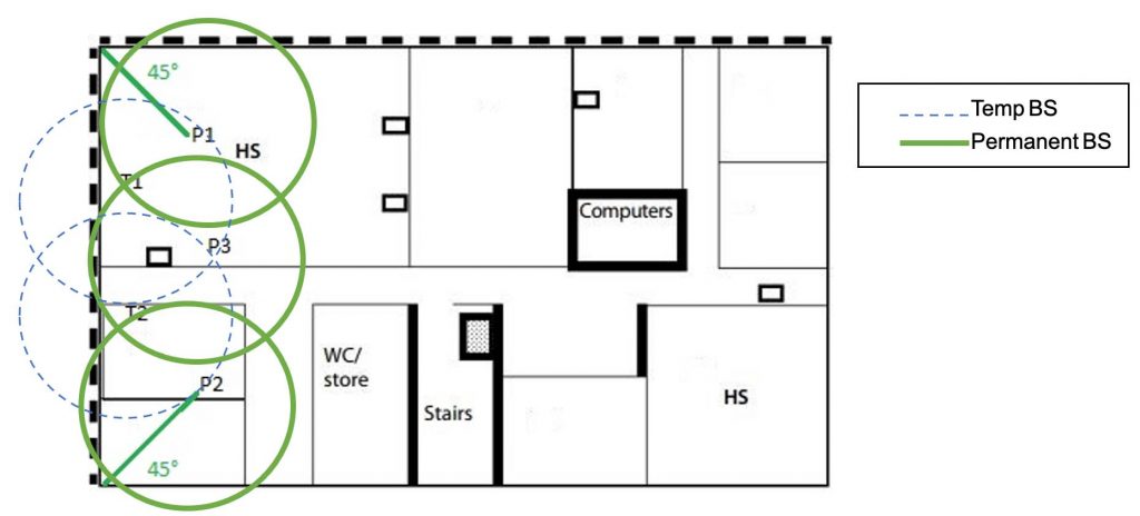
Figure 4: Wide Area Deployment
Multi Floor Buildings
For multi-floor buildings, users could deploy base stations on different floors while taking into consideration and measuring the horizontal coverage of base stations that spans through ceilings. But usually this is not the case since most ceiling material is composed on metal and reinforced concrete and studies shows that this kind of material introduces up to 90% loss of the radio signal in comparison to free wireless field.
Knowing this, users could consider treating each floor separately and follow the instructions described on single floor deployment section.
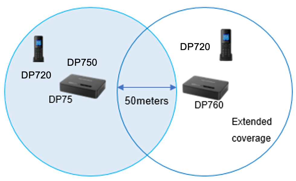
Using DECT Repeater
The DP760 is a powerful DECT Repeater that auto associates to Grandstream DP75x Base Station to offer extended coverage to business and residential users. It extends an additional range of 300 meters outdoors and 50 meters indoors to give users the freedom to move around while delivering efficient flexibility.
Pairing DP760 with DP75x Base Station
Step 1: Enabling Repeater Mode on DP75x
Before associating the DP760 DECT Repeater to your DP75x Base Station, you should firstly enable the repeater mode on your base station. Please refer following steps to enable the repeater mode on the DP75x base station:
- Access DP75x Web GUI using the admin’s username and password. (Default username and password is: admin/admin).
- Navigate to DECT 🡪 General Settings and set Enable Repeater Mode to Yes then save and reboot.
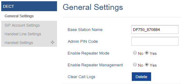
Figure 5: Enable Repeater Mode
Step 2: Open the Subscription Process
- Open the subscription on DP75x and DP760 either using the web GUI or via the Subscribe button.
- Make sure to install the DP760 next to DP75x to be discovered.
Step 3: DP760 DECT Repeater Association
After enabling the repeater mode on DP75x Base Station, you can easily associate it with your DP760 DECT Repeater using one of the following methods:
- Auto Association
- Manual Association (Using DP760 web GUI to manually specify the address of the base).
- Repeater Management Mode (Using DP75x web GUI to manage discovered repeaters).
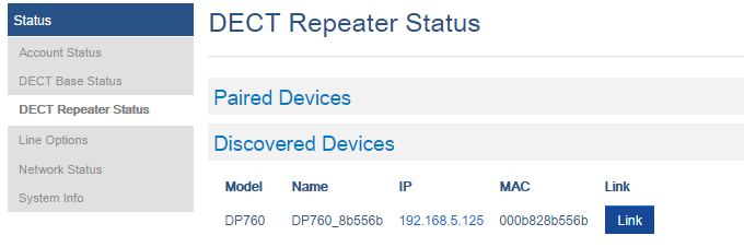
Figure 6: DECT Repeater Status on DP75x
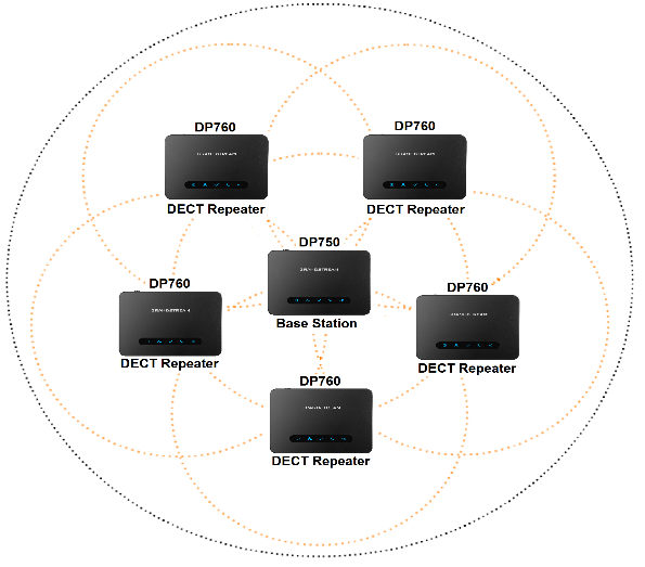
Deploying DP760 Repeater
DP75x Base Station can support up to 5 DP760 DECT Repeater stations to extend the coverage area of the base in all directions. When the repeater powers on, it searches for signals from the base and any other repeaters registered to the same base and it will automatically connect to the strongest available signal.
The base can hand-off calls to the repeaters as the user moves from one coverage area to another. When connected to the repeater, the DP720 handsets operate as it’s connected to the base, and the hand-off from the base to the repeater can be completely invisible to the end user, even during an active call.
Important Note: DP760 can relay up to 2 concurrent calls.
Users will need to have the repeater close the base station during the pairing process, and once pairing is successful the repeater can be moved far away to its intended placement where it will replicate the weak signal over the non-covered areas. But in the same time the repeater should be close to the base station in order to have enough coverage overlap for better synchronization.
We recommend having a distance within 50 meters between the repeater and the base, so that the repeater stays within the base range.
ON-SITE MEASURING
Installing Base Station
After planning the actual locations for the base stations, it is recommended to confirm the circumstances using on-site measurements. Usually, base stations must be spaced out at intervals of approximately 2.5m horizontally when deploying multiple bases and an ideal height between 2m and 2.5m.
It is recommended as well to have base stations close to the center of the area as much as possible.
For outdoor deployments, also better to choose a central position and make sure that the chosen location is protected from the weather and corresponds to the type of protection of the outdoor base station. The installation site is chosen sufficiently high to be protected from acts of vandalism.
For indoor deployments, avoid installing the base station near cable ducts, metal cabinets and other large metal objects. Also, customer’s aesthetic aspects and wishes could be considered.
Using Handset for Reception Measurement
During the measurement process, users could use the factory function provided by DP720 handset in order to measure the value of the received signal strength RSSI which will help assess the quality of transmission around the site.
The value of the RSSI is expressed in dBm and below table gives an initial guideline for the quality of the wireless connection for various RSSI values:
Table 6: RSSI Values Evaluation
RSSI value | Evaluation of the quality |
-50 dBm | Very Good |
-60 dBm | Good |
-65 dBm | Satisfactory |
-70 dBm | Adequate |
-73 dBm | Weak, not suitable |
-76 dBm | Poor, not suitable |
Note: Usually a value of (-70dBm) is acceptable and the signal should not be weaker than that.
Users can follow below steps to measure signal strength by checking the RSSI indicator from the DP720:
- Install the measuring base station into its intended placement and power on the measuring handset.
- Factory reset both handset and base station and make sure that the handset is properly charged.
- Pair the handset with the base station.
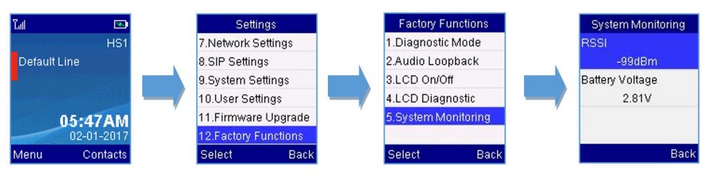
- Once the registration done navigate to Menu>Settings>Factory Functions>System Monitoring.
- The value of RSSI should be displayed at the top as illustrated on the following figure:
Test Calls and Optimization
Along with the measurement of the signal quality to determine the coverage range of each base station and repeater, the user is highly recommended to make test calls and access voice quality.
After installing the base station, make sure to pair two testing handsets to proceed with the test calls.
After setting up the base and the testing handsets, the users can start a test call and access the following parameters:
- Voice quality and clearance.
- Flexible mobility (no call drop while moving around the area).
- Seamless hand off calls when repeaters are used.
- Capacity in term of number of calls: users can make several concurrent calls and determine that the intended capacity is satisfied.
After this is done, and with results of the signal strength measurements the user can mark any remaining dead spots on the site for optimization.
- More base stations or repeater can be introduced to help cover dead spots.
- Customer can be and advised to avoid making calls on such areas.