
Overview
The GSC3516 is a SIP intercom speaker and microphone that allows offices, schools, hospitals, apartments, and more to build powerful voice intercom solutions that expand security and communication. This robust SIP intercom device offers 2-way voice functionality with both a high-fidelity 15W HD speaker and 3 directional microphones with Multichannel Microphone Array Design (MMAD) and 1 omnidirectional auxiliary microphone that offers a 4.2-meter pickup distance. The GSC3516 supports a wide range of peripherals including Bluetooth devices, a built-in whitelist, and blacklists to easily block unwanted calls, integrated dual-band Wi-Fi, and advanced acoustic echo cancellation. By pairing the GSC3516 with other Grandstream devices, including desktop and cordless IP phones as well as the GDS series of Facility Access products, users can easily sculpt a state-of-the-art security and voice intercom solution. Thanks to its modern industrial design, a cleanable exterior surface, and rich features, the GSC3516 is the ideal intercom speaker/microphone for any setting.
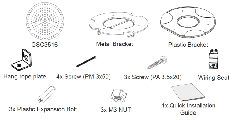
Package Contents
GSC3516 Ports

Port | Label | Description |
 | Reset | Factory reset button. |
 | NET/PoE | Ethernet RJ45 port (10/100Mbps) supporting PoE/PoE+. |
 | 2-Pin port | Ethernet RJ45 port (10/100Mbps) supporting PoE/PoE+. |
Hardware Installation
GSC3516 can be mounted on the wall or ceiling. Please refer to the following steps for the appropriate installation.
Wall Mount
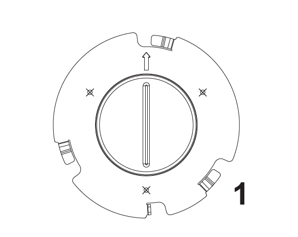
- Locate the equipment holder in the desired position with the arrow up. Drill three holes on the wall referring to the positions of holes on the metal bracket.
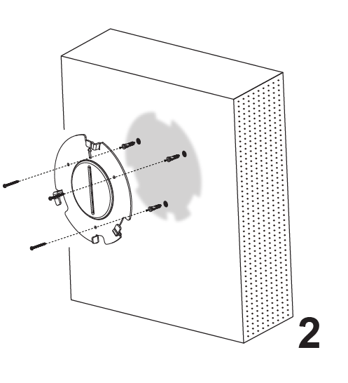
2. Fix the metal bracket on the wall with expansion screws.
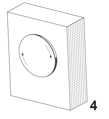
3. Align the position line on the device’s back cover with the positioning slot.
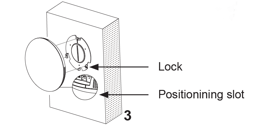
4. Rotate the device clockwise until it is locked in the right position.
Ceiling Mount
- Put the ceiling mounting (metal bracket) in the ceiling’s center and mark the position of the three screw holes.
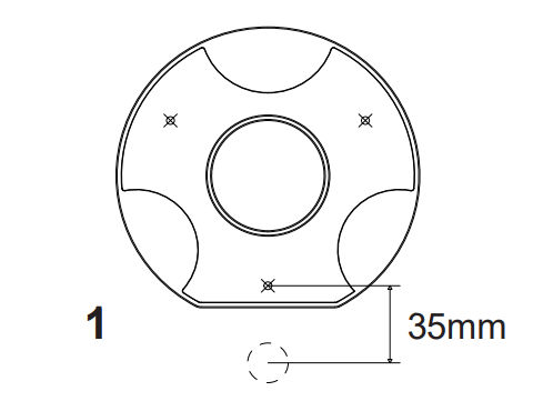
2. Drill a round hole with a diameter of 18mm for the Ethernet cable. The distance between its center and the highlighted hole on the plastic bracket should be 35mm.

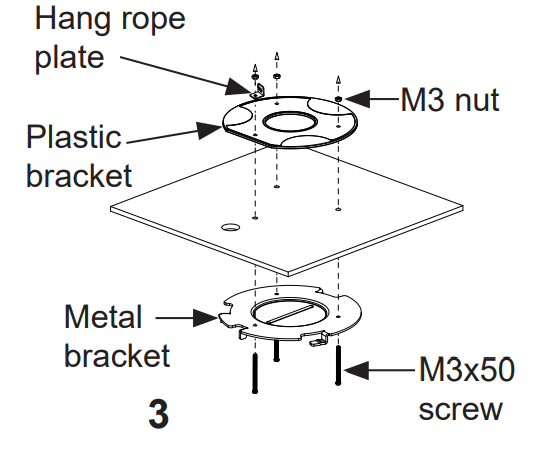
3. Fix the plastic and metal brackets on the ceiling with flat-head screws and locknuts. Then place an Ethernet cable pass through the 18mm-round hole.
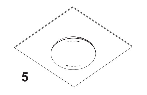
4. Align the position line on the device’s back cover with the positioning slot.
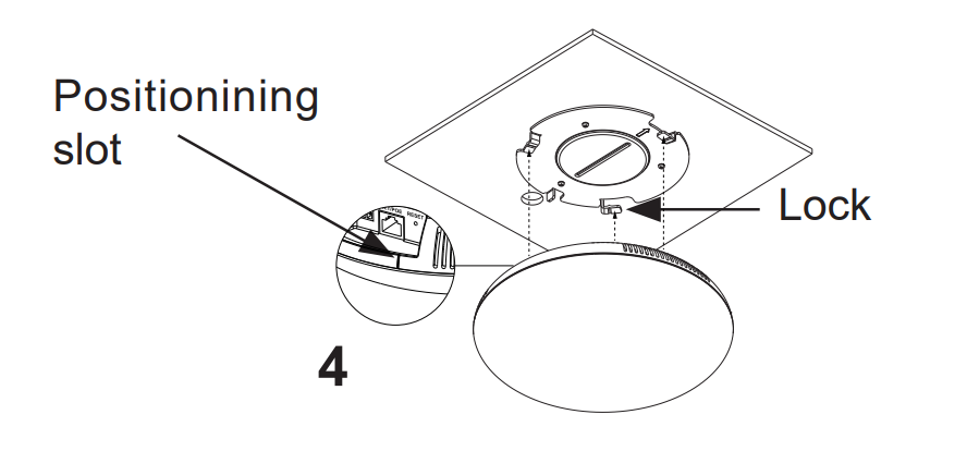
5. Rotate the device clockwise until it is locked in the right position.
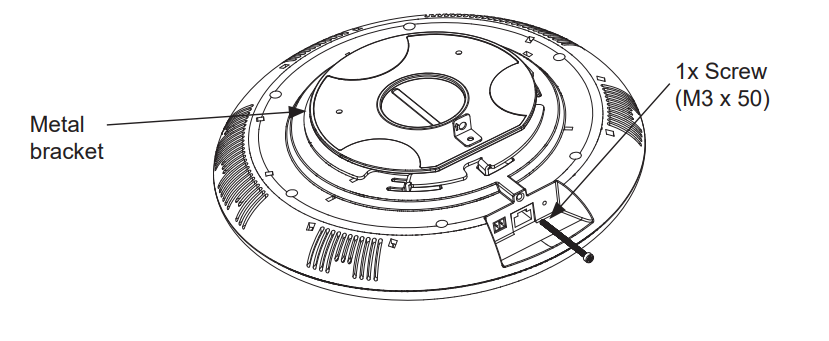
Anti-theft Installation
After the device is assembled with the metal bracket support on the wall or ceiling, use the anti-detachable screw (M3 x 50) in order to prevent theft.
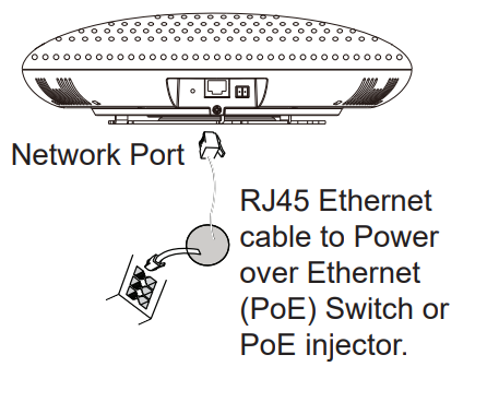
Powering and Connecting GSC3516
GSC3516 can be powered on using PoE/PoE+ switch or PoE injector using the following steps:
Step 1: Plug an RJ45 Ethernet cable into the network port of the GSC3516.
Step 2: Plug the other end into the power over Ethernet (PoE) switch or PoE injector.
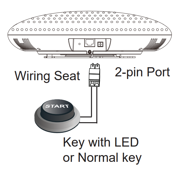
Connecting Wiring Seat
GSC3516 support connecting a “Key & LED” or “Normal Key” to the 2-pin port via Wiring Seat.
Step 1: Take the wiring seat from the install kits.
Step 2: Connect the Key & LED or Normal Key with the wiring seat (as shown in the illustration on the right).
Accessing the Configuration Interface
A computer connected to the same network as the GSC3516 can discover and access its configuration interface using its MAC address :
- Locate the MAC address on the MAC tag of the unit, which is on the underside
of the device, or on the package. - From a computer connected to the same network as the GSC3516, type in the following address using the GSC3516’s MAC address on your browser: http://gsc_<mac>.local
Example: if a GSC3516 has the MAC address C0:74:AD:11:22:33, this unit can be accessed by typing http://gsc_c074ad112233.local on the browser.


For Certification, Warranty, and RMA information, please visit
www.grandstream.com