Overview
The term “multi-layer switching” in the context of a Layer 3 network switch refers to the capability of the switch to operate at both Layer 2 (Data Link Layer) and Layer 3 (Network Layer) of the OSI model. In a traditional Layer 3 switch, the primary function is routing at Layer 3, which involves making forwarding decisions based on IP addresses.
However, multi-layer switching takes it a step further by incorporating features of both Layer 2 switching (based on MAC addresses) and Layer 3 routing (based on IP addresses). This integration allows the GWN78xx switches to make intelligent forwarding decisions not only at the network layer but also at the data link layer, resulting in improved efficiency and performance.
In this guide, we will walk through the configuration of a GWN78xx multilayer switch, connected to access switches that will result in an inter-VLAN routing.
Inter-VLAN Routing Types
In a network consisting of diverse devices distributed across different VLANs, challenges may appear when these devices require to communicate with each other, in what we call inter-VLAN communication. Traditional Layer 2 switches lack the capability for such communication, requiring an external routing mechanism that is usually a router. This problem is addressed by multi-layer switches, such as the GWN78xx series, which seamlessly integrates Layer 2 switching based on MAC addresses and Layer 3 routing based on IP addresses. This eliminates the need for conventional VLAN routing methods like “router on a stick”, instead, the multi-layer switching method uses SVI( switching VLAN interfaces) to differentiate between different VLANs connected on the network.
Inter-vlan routing can be configured based on three different types which are :
- Traditional Inter-VLAN Routing
- Router on a Stick Inter-VLAN Routing
- Multi-layer Switch Inter-VLAN Routing
The table below summarizes some of the main differences between the types of inter-VLAN Routing:
Aspect | Traditional Inter-VLAN Routing | Router on a Stick Inter-VLAN Routing | Multi-layer Switch Inter-VLAN Routing |
Device Used | Dedicated router. | Single router interface (sub-interfaces). | Layer 3 switch. |
Method | Each VLAN connects to a separate physical router interface. | A single physical connection (trunk) carries traffic for multiple VLANs. | The switch performs both Layer 2 switching and Layer 3 routing. |
Complexity | Higher complexity due to multiple physical connections. | Simplifies cabling but relies on a single connection for multiple VLANs. | Simplifies network design by integrating Layer 2 and Layer 3 functions. |
Scalability | May become complex and less scalable as the number of VLANs increases. | More scalable than traditional inter-VLAN routing but still has limitations. | Highly scalable due to the switch's ability to perform routing at wire speed. |
Performance | Can introduce bottlenecks, especially with a large number of VLANs. | Can be a bottleneck for high traffic volumes. | Typically provides better performance compared to traditional methods. |
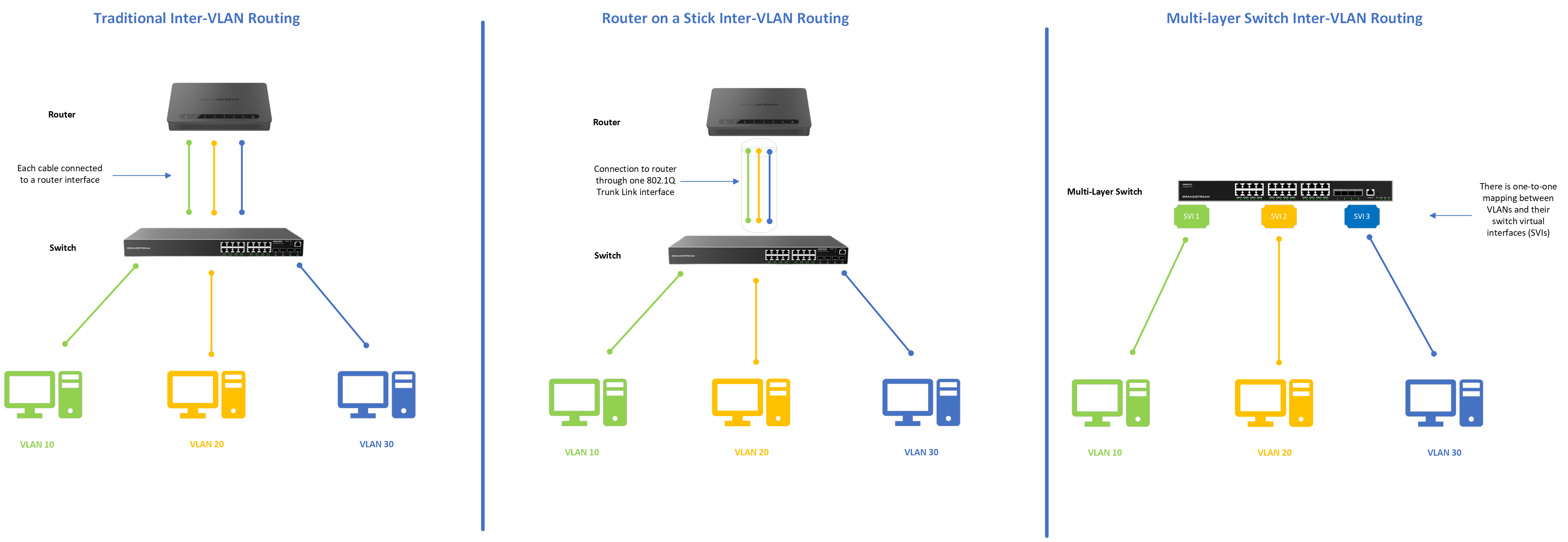
Comparing the inter-VLAN routing methods
Below is an illustration showing the differences between each Inter-VLAN Routing type
Configuration example
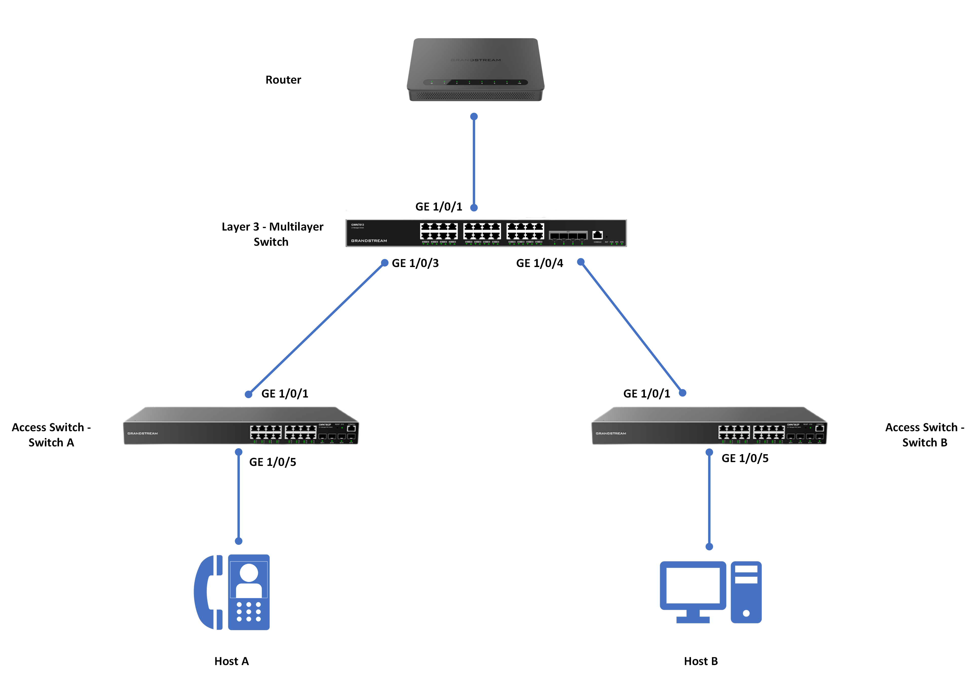
Consider the following topology:
In this guide, we will configure the multi-layer switch to connect to two different access switches that will pass traffic from different VLANs, and the two hosts connected to these different switches will be able to ping each other to make sure that the communication is successful, this will imply that we have inter-VLAN routing configured correctly.
Switch A Configuration
First, we will start by configuring Switch A to accept VLAN10 traffic coming from the multi-layer switch, to do that :
- Go to Switch A Web UI, and access Switching → VLAN
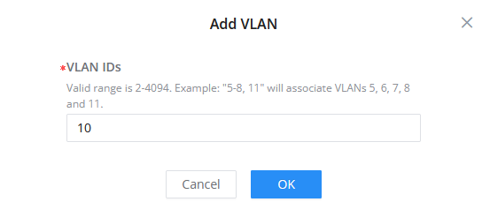
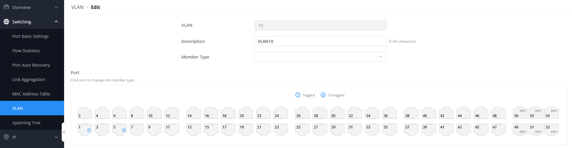
- Create VLAN 10 by clicking
 and giving it the reference 10
- Select port 1/0/1 to be tagged port since it will be the port connected to the Multilayer switch.
- Select port 1/0/5 to be the untagged port since it will be the port connected to Host A.
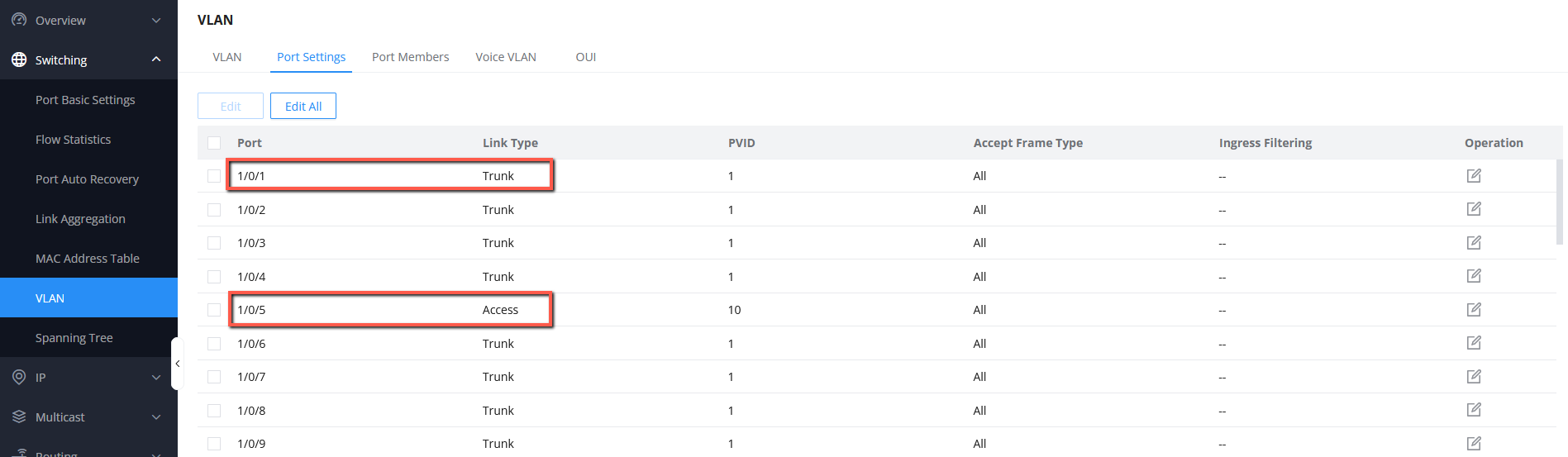
- On Switching → VLAN → Port settings, make sure that port 1/0/1 is set to trunk port, and port 1/0/5 is set to be access port.
Switch B Configuration
In the same way, we will configure Switch B to accept the VLAN 20 tag configured on the multi-layer switch:
- Go to Switch B Web UI, and access Switching → VLAN
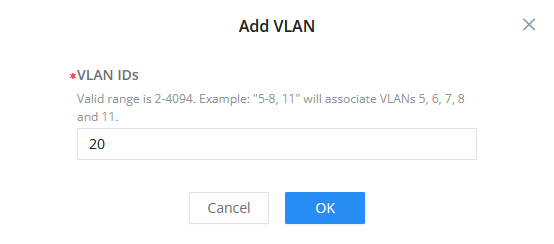
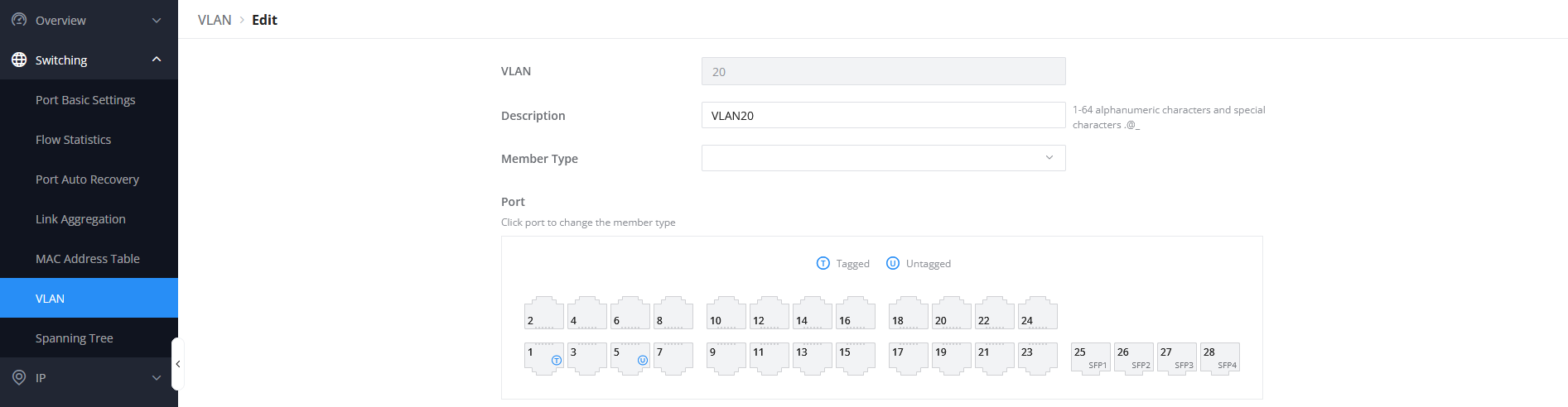
- Create VLAN 20, by clicking and giving it the reference 20
- Set port 1/0/1 to be tagged port, since it will be connected to the multi-layer switch, and port 1/0/5 to be untagged port since it will be connected to Host B.
- On Switching → VLAN → Port settings, make sure that port 1/0/1 is set to trunk port, and port 1/0/5 is set to be access port.
Multi-Layer Switch Configuration
In this section, we will configure the Multi-Layer Switch to assign specific IP addresses based on the VLAN interface on which the endpoints will be connected, this will include the following steps:
- Creating VLAN 10 and 20, and setting trunk links to the connected access switches A and B.
- Setting up VLAN IP interfaces, also known as Switch Virtual Interfaces (SVIs).
- Enabling DHCP service and creating an IP assignment pool for each VLAN.
- Verifying if the connected devices on ports 1/0/5 of each switch can take the IP from the defined range.
Step 1: Creating VLAN 10 and 20
- On the multi-layer switch Web UI, Access Switching → VLAN
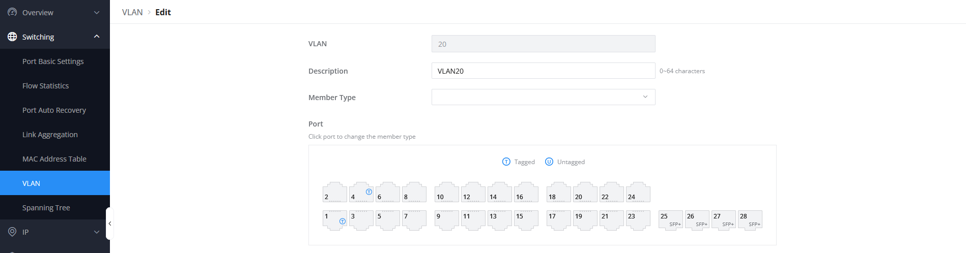
- Create two VLANs 10, and 20 by clicking , and setting the VLAN ID respectively to VLAN ID 10 and VLAN ID 20
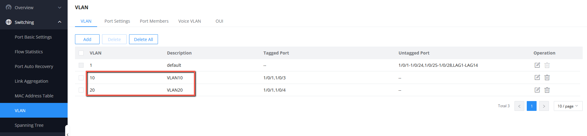
- On VLAN 10, set port 1/0/1 to be a tagged port (trunk port), this port will be connected to the network edge router, and set port 1/0/3 to be a tagged port (trunk port), this port will be connected to the access Switch A

- With the same method, on VLAN 20, set port 1/0/1 to be a tagged port (trunk port), this port will be connected to the network edge router, and set port 1/0/4 to be a tagged port (trunk port), this port will be connected to the access switch B
Step 2: Creating VLAN IP Interfaces (SVIs) for VLAN 10 and 20
- On the multi-layer switch Web UI, Access IP → VLAN IP Interface
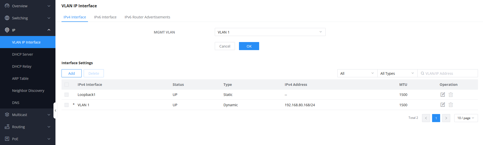
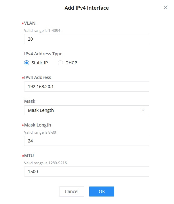
- Create two VLAN interfaces by clicking : VLAN 10 and VLAN 20, set the IPv4 address of VLAN 10 to 192.168.10.1 this will be the VLAN 10 default gateway,
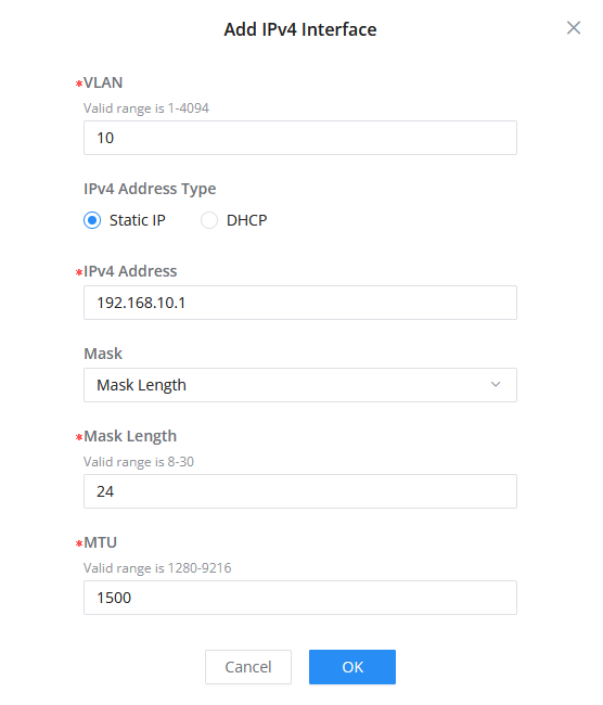
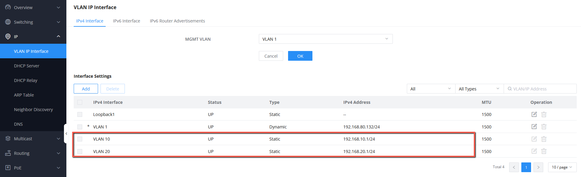
- In the same way, set the VLAN 20 IP address to 192.168.20.1, and make sure to set the network mask of both IP addresses to /24
- Both VLAN interfaces will be displayed alongside the default VLAN 1.
Step 3: Enable DHCP Service and Create IP Address Pool
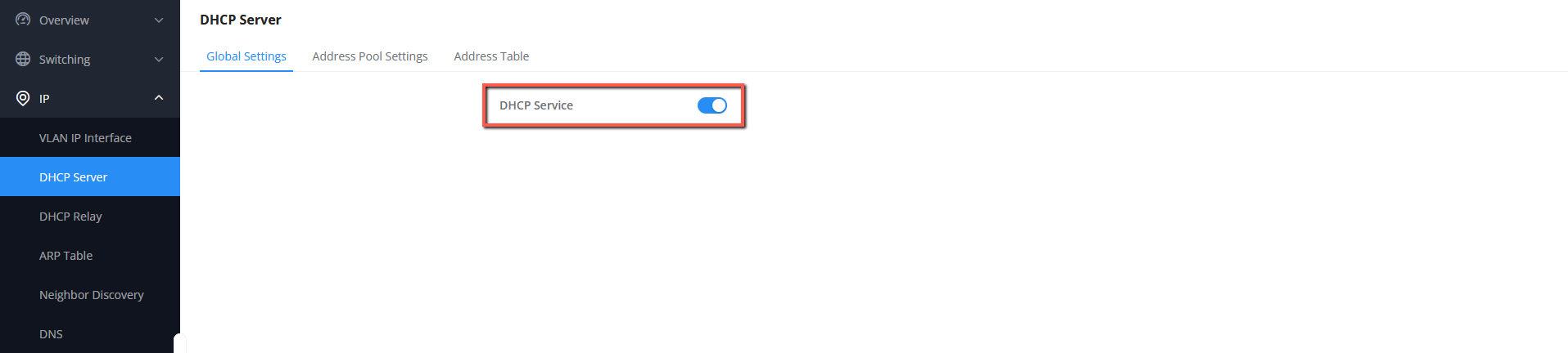
- On the web UI of the multi-layer switch, Go to IP → DHCP Server → Global Settings
- Enable DHCP Service
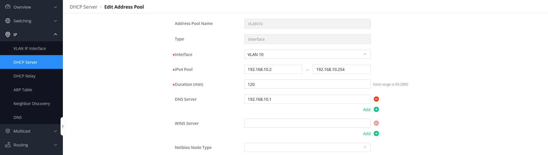
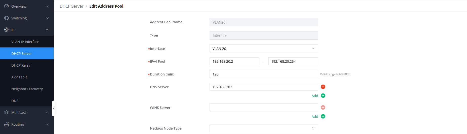
- Go to IP → DHCP Server → Address Pool Settings
- Add the Address pool for VLAN 10 and set it to be on the range 192.168.10.2-192.168.10.254, this will assign IP addresses for connected devices on VLAN 10 with the network part 192.168.10.x
- In the same way, set the address pool range for VLAN 20 to 192.168.20.2-192.168.20.254, this will assign IP addresses for connected devices on VLAN 20 with the network part 192.168.20.x
- Click save to save the global settings.
Step 4: Verifying IP Assignment
- After the configuration is completed, Plug Host A on Switch A interface 1/0/5, the device should take an IP on network 192.168.10.x
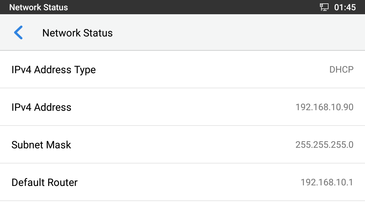
- In the same way, Host B will take IP on network 192.168.20.x
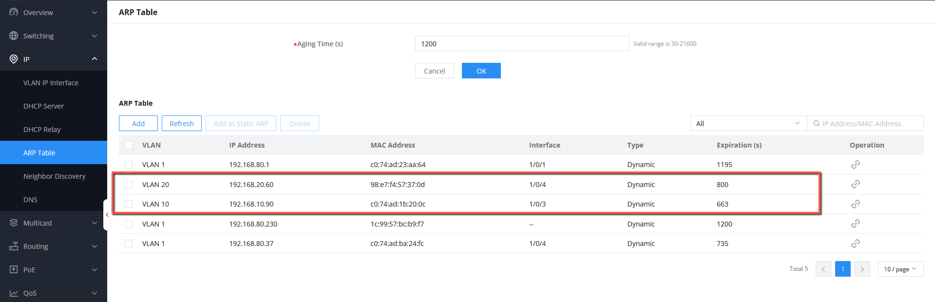
- You can also check the IP address assignment from the ARP table, to do that access the switch web UI, IP → ARP Table, and the list of connected devices, with their respective VLAN, IP address, and MAC address will be displayed
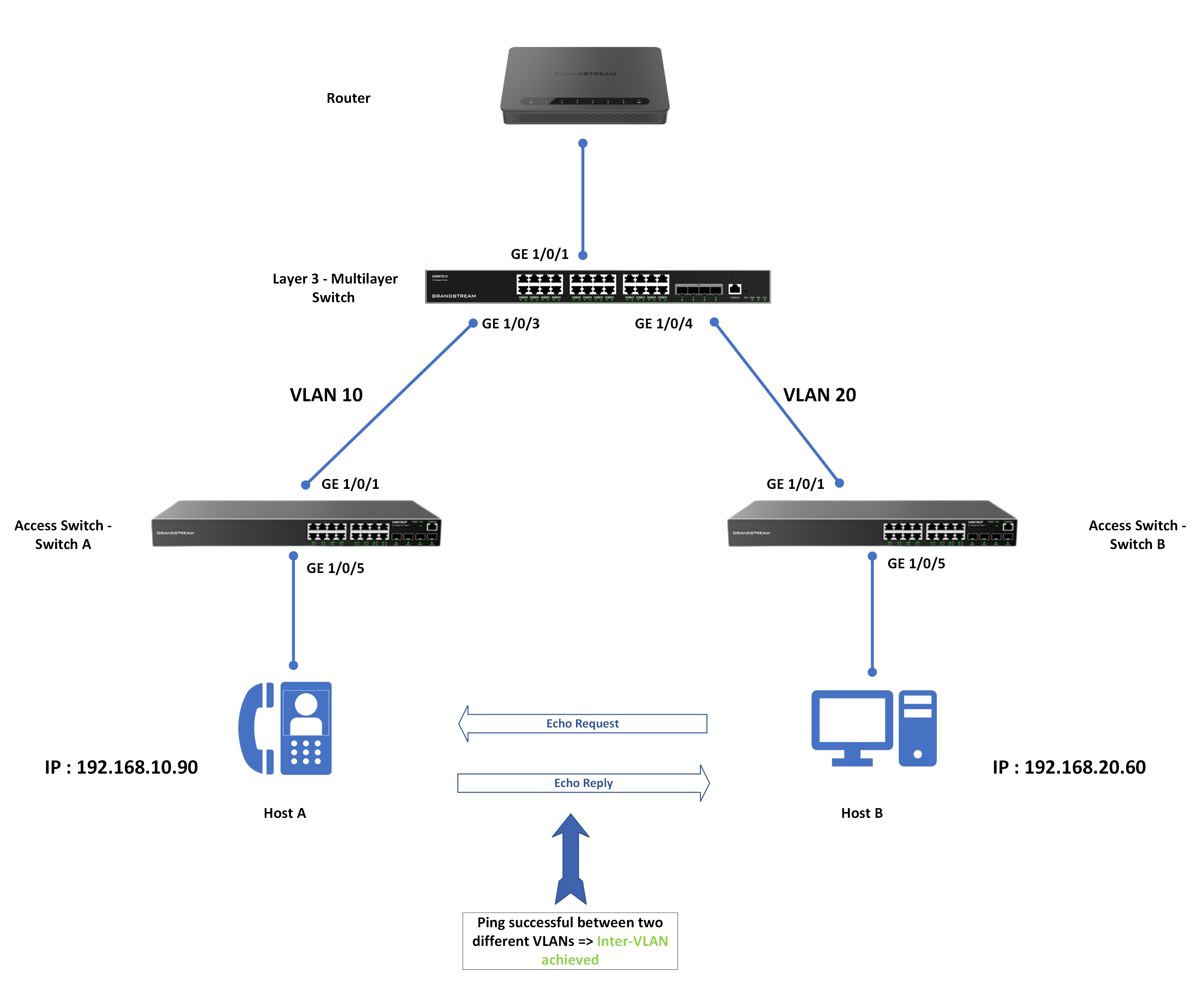
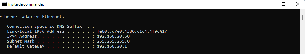
Testing the Communication
After the setup is completed and the trunks are well established, we can verify if inter-vlan routing is working correctly on the multi-layer switch by running a ping from Host B with IP address 192.168.20.60 to Host A with IP Address 192.168.10.90, if the ping is successful it means that the devices can communicate while being at different VLANs, and Inter-VLAN routing is achieved through the GWN78xx Layer 3 switch.
Verifying a ping from Host B to Host A
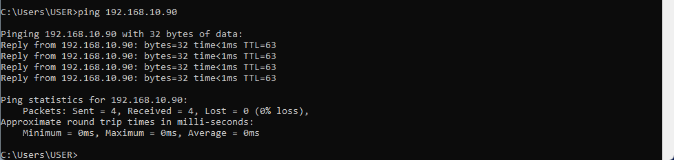
We can see that the ping is successful, hence the configuration is completed.
Supported Devices
Device Name | Supported | Firmware Required |
GWN7801 | Yes | 1.0.3.19 or higher |
GWN7801P | Yes | 1.0.3.19 or higher |
GWN7802 | Yes | 1.0.3.19 or higher |
GWN7802P | Yes | 1.0.3.19 or higher |
GWN7803 | Yes | 1.0.3.19 or higher |
GWN7803P | Yes | 1.0.3.19 or higher |
GWN7811 | Yes | 1.0.1.8 or higher |
GWN7811P | Yes | 1.0.1.8 or higher |
GWN7812P | Yes | 1.0.1.8 or higher |
GWN7813 | Yes | 1.0.1.8 or higher |
GWN7813P | Yes | 1.0.1.8 or higher |
GWN7806 | Yes | 1.0.1.14 or higher |
GWN7806P | Yes | 1.0.1.14 or higher |
GWN7816 | Yes | 1.0.3.8 or higher |
GWN7816P | Yes | 1.0.3.8 or higher |
GWN7830 | Yes | 1.0.3.3 or higher |
GWN7831 | Yes | 1.0.3.3 or higher |
GWN7832 | Yes | 1.0.3.3 or higher |
List of supported devices