OVERVIEW
The WP820 is a portable Wi-Fi phone designed to suit a variety of enterprises and vertical market applications, including retail, logistics, medical and security. This powerful, portable Wi-Fi phone comes equipped with integrated dual-band 802.11a/b/g/n Wi-Fi support, advanced antenna design and roaming support, and integrated Bluetooth for pairing with headsets and mobile devices. With the growing coverage of Wi-Fi network, wireless access point (AP) is now widely used for small/medium enterprises, multiple-floor offices, commercial locations and branch offices to provide seamless Wi-Fi access and mobile solutions. This document provides a guideline for network administrator to deploy WP820 in different Wi-Fi environment to achieve the best communication quality.
WP820 WI-FI FREQUENCY AND CHANNEL
The WP820 has built-in dual-band 802.11a/b/g/n Wi-Fi support. Below frequency and channels are supported.
Table 1: WP820 Frequency and Channels
Peak Antenna Gain | Frequency Ranges | Available Channels | Channel Set |
2.4GHz=2.4 dBi 5GHz=3.0 dBi | 2.412 – 2.472 GHz 5.180 – 5.240 GHz 5.260 – 5.320 GHz 5.500 – 5.720 GHz 5.745 – 5.825 GHz | 14 4 4 12 5 | 1-13 36, 40, 44, 48 52, 56, 60, 64 100-140 149, 153, 157, 161, 165 |
WP820 WI-FI ROAMING
To adapt to different Wi-Fi deployment, WP820 has provided several roaming options for users to configure. Below options are available under LCD menu->Settings->Network settings->Wi-Fi roaming mode. They can also be found in WP820 Web GUI->Network Settings->Wi-Fi Settings->Wi-Fi Roaming page.
Table 2: WP820 Wi-Fi Roaming Options
|
Name |
Description |
|
Signal threshold |
Sets the Wi-Fi signal threshold. When the Wi-Fi signal strength of the device drops below this configured value, the device will scan for a hotspot above the threshold value and connect to it. The default setting is -70 and the valid range is [-100, -30]. |
|
Good signal scan interval |
Sets the time interval for signal scanning when the Wi-Fi signal strength is higher than the signal threshold. Default is 600s, and valid range is from 5to 600. |
|
Poor signal scan interval |
Sets the time interval for signal scanning when the Wi-Fi signal strength is lower than the signal threshold and there is no hotspot which is higher than the current signal strength. Default is 5s, and valid range is from 5 to 600. |
When the AP that WP820 is currently connected to has signal strength lower than the configured “Signal threshold” on WP820, the device will try to look for a nearby AP with better RSSI. To avoid switchover back and forth due to unstable RSSI, the WP820 will only switch over when the new AP’s RSSI is at least 8 dB higher than the currently connected AP.
“Good signal scan interval” and “Bad signal scan interval” determine the scan interval for WP820 to find out whether there is a better AP nearby to switch to. Normally if the currently connected AP has a higher RSSI than the threshold, WP820 can scan at a longer interval, while a shorter value can be applied for “Poor signal scan interval” because the currently connected AP has lower RSSI than the threshold which means WP820 should look for a better AP in a more aggressive way.
DEPLOYMENT REQUIREMENTS
When deploying Wi-Fi network with multiple APs for WP820 to roam, please follow below guidelines:
- Make sure the APs are properly powered up and connected to your network.
- Connect your PC to the same network as the APs. This PC is used for configuring the APs and other necessary devices via web GUI.
- Access the APs using the PC’s web GUI. Configure the APs to set them up.
- Set the same SSIDs for all the APs. SSID is case sensitive.
- Make sure the IP addresses assigned by the APs belong to the same network segment and the same VLAN.
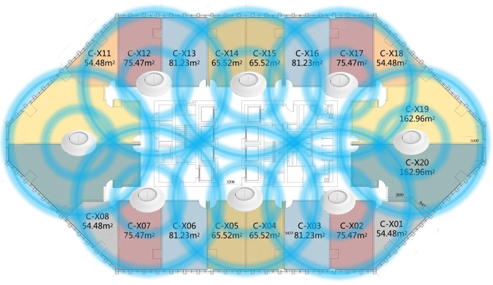
During deployment, the cell edge for each AP should be designed to -67dBm and there should be 20% – 30% overlap between adjacent APs at that signal level. Otherwise, WP820 might encounter packet loss or blind area at the cell edge and it cannot hold the signal long enough to complete seamless switchover. To ensure seamless roaming, it’s recommended that WP820 can always receive RSSI -67dBm or higher from the access point.
IMPORTANT WI-FI PARAMETERS ON AP
There are several important parameters on AP for Wi-Fi configuration. Configuring them properly will enhance WP820 roaming performance.
Beacon Interval
Beacon interval defines how often the AP transmits the 802.11 beacon management frames. Usually the default value is 100ms. It’s recommended to keep it as default value on AP.
DTIM
This is the Delivery traffic indication message (DTIM) period in beacons. It’s recommended to set it to 2.
Unicast Mode and Multicast Mode
In unicast mode, the controller unicasts every multicast packet to every access point associated to the controller. In multicast mode, the controller sends multicast packets to a CAPWAP multicast group. This method reduces overhead on the controller processor and shifts the work of packet replication to your network. It’s recommended to use unicast mode to ensure call quality.
WMM (Wi-Fi Multimedia)
WMM is a wireless QoS protocol, a subset of the 802.11e protocol. It is used to ensure that packets with high priority can be sent first so that service quality for voice, video and other applications can be guaranteed.
On WP820, WMM related configurations can be found undero web UI->Network Settings->Advanced Network Settings.
- Layer 3 QoS for SIP
This defines the layer 3 packet’s QoS parameter for SIP messages in decimal pattern. The value is used for IP Precedence, Diff-Serv or MPLS. The default setting is 26 which is equivalent to the DSCP name constant CS6.
- Layer 3 QoS for Audio
This defines the layer 3 packet’s QoS parameter for RTP messages in decimal pattern. This value is used for IP Precedence, Diff-Serv or MPLS. The default setting is 46 which is equivalent to the DSCP name constant CS6.
WP820 will convert the QoS value to the corresponding WMM value/level so the packets can be differentiated and handled properly by other network devices.
Band Steering
Dual band operation with Band Steering detects clients capable of 5 GHz operation and steers them to that frequency which leaves the more crowded 2.4 GHz band available for legacy clients. This helps improve end user experience by reducing channel utilization, especially in high density environments. It’s recommended to enable band steering on the APs, which means by default 5Ghz should be used (users can switch to 2.4Ghz if 5Ghz signal is poor.)
For above important parameters, the following sections provide the configuration methods on APs from different vendors for network administrator’s quick reference. The following table shows whether the AP has the configurations related to these parameters. Click on the brand name to quickly locate relevant configuration instructions.
Table 3: Important Wi-Fi Parameters
|
Product Model |
Roam |
Band Steering | ||||
|
GWN76XX |
√ |
√ |
√ |
√ | ||
|
CISCO MERAKI |
√ |
√ |
√ | |||
|
ARUBA CENTRAL |
√ |
√ |
√ |
√ |
√ | |
|
√ |
√ | |||||
|
UBIQUITI UNIFI |
√ |
√ |
√ | |||
|
MIST |
√ |
√ |
√ | |||
|
√ |
√ |
√ | ||||
|
EZMASTER |
√ | |||||
|
CLOUDTRAX |
√ |
√ | ||||
|
TP-LINK |
√ |
√ |
√ |
√ |
√ |
GWN76XX
Wireless Configuration
- Open a web browser on PC and enter the GWN web address to access the GWN76XX web UI configuration page.
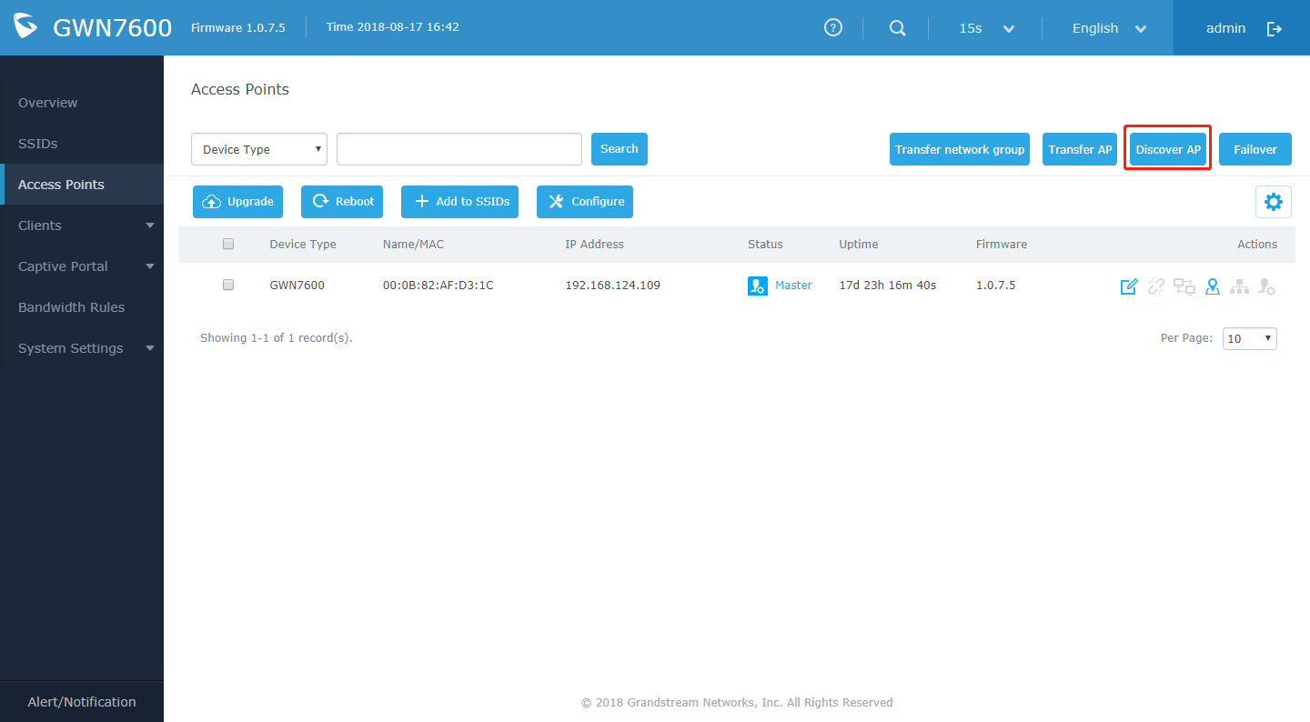
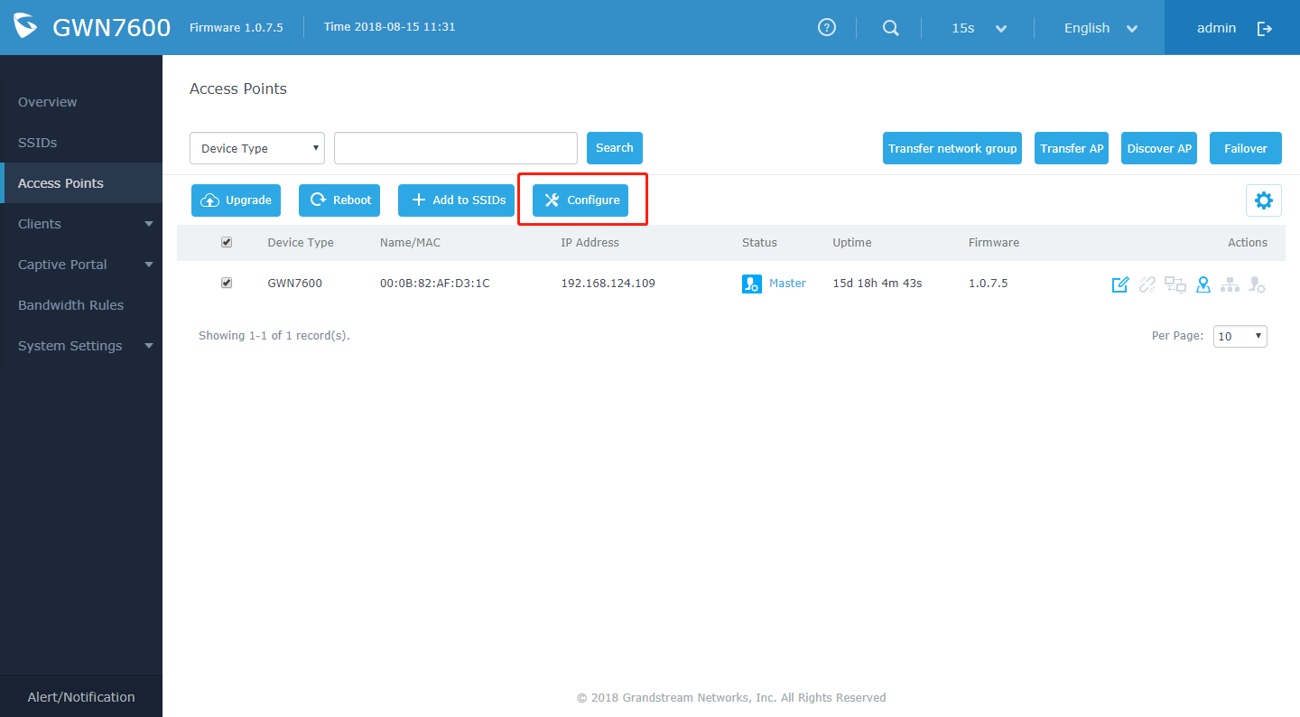
- Connect to the GWN76XX Web GUI as Master and navigate to page “Access Points”.
- Click on Discover AP.
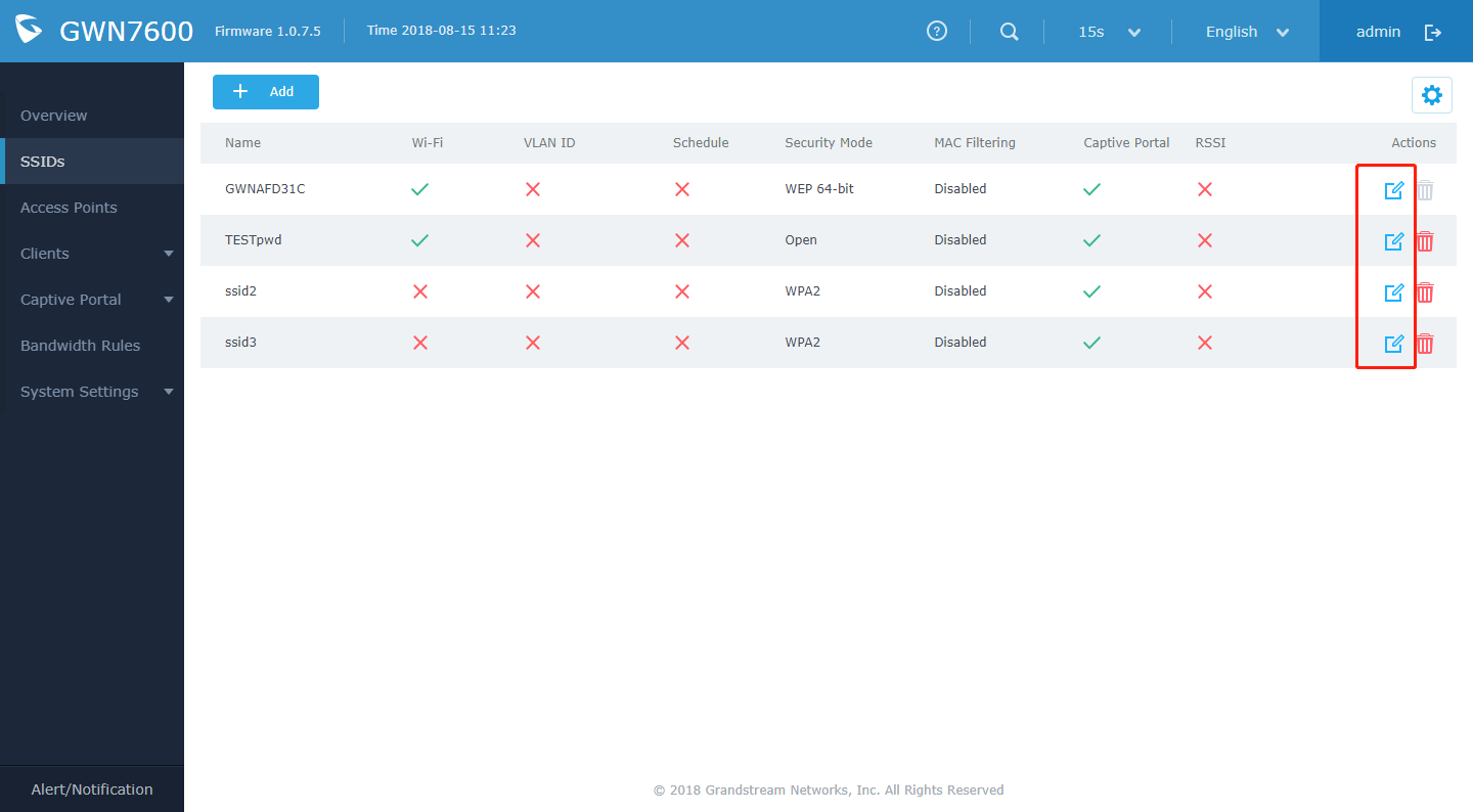
- When using GWN76XX as Master Access Point, users have the ability to create different SSIDs and adding GWN76XX Slave Access Points. Click on Edit to edit the SSID.
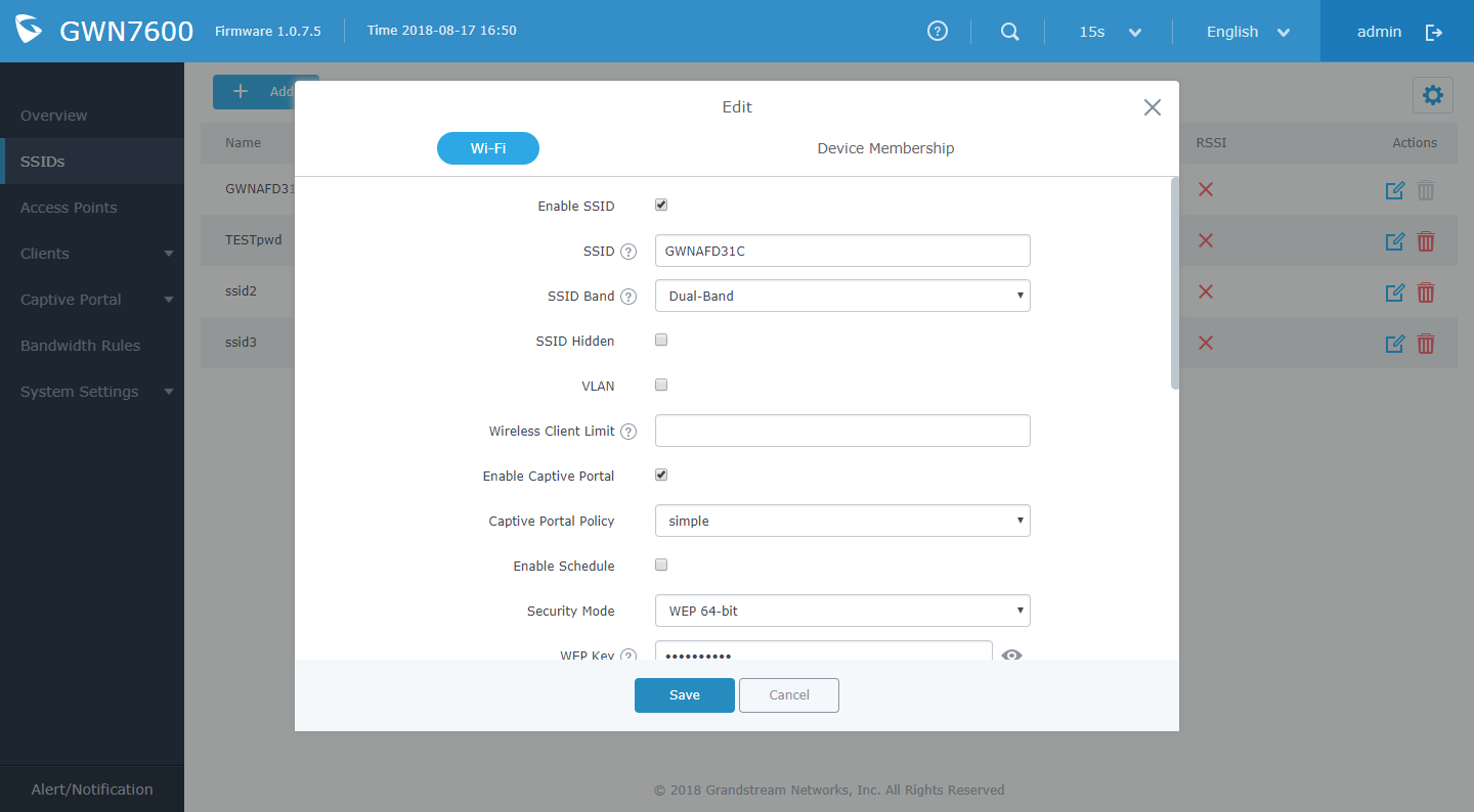
- When editing or adding a new SSID, users will have to configure Wi-Fi. Please refer to below table for Wi-Fi tab options.
Table 4: GWN7000 Wi-Fi Parameters
|
Description | |
|
Enable SSID |
Check to enable Wi-Fi for the SSID. |
|
SSID |
Set or modify the SSID name. |
|
Select the Wi-Fi band the GWN will use, three options are available:
| |
|
SSID Hidden |
Select to hide SSID. SSID will not be visible when scanning for Wi-Fi, to connect a device to hidden SSID, users need to specify SSID name and authentication password manually. |
|
VLAN |
Enter the VLAN ID corresponding to the SSID. |
|
Configure the limit for wireless client. If there’s an SSID per-radio on a SSID, each SSID will have the same limit. So, setting a limit of 50 will limit each SSID to 50 users independently. If set to 0 the limit is disabled. | |
|
Enable Captive Portal |
Click on the checkbox to enable the captive portal feature. |
|
AP will remove the client’s entry if the client generates no traffic at all for the specified time period. The client inactivity timeout is set to 300 seconds by default. Range from 60-3600 seconds. | |
|
Captive Portal Policy |
Select the captive portal policy already created on the Policy List web page to be used in the created SSID. |
|
Enable Schedule |
Check the box and choose a schedule to apply for the selected SSID. |
|
Security Mode |
Set the security mode for encryption, 5 options are available:
Note: GWN products support for 802.1x (PEAP-MSCHAPv2 and EAP-TLS) requires external AAA server to permit authentication and centralized access management. |
|
WEP Key |
Enter the password key for WEP protection mode. This field is available only when “Security Mode” is set to “WEP 64-bit” or “WEP 128-bit”. |
|
WPA Key Mode |
Two modes are available:
This field is available only when “Security Mode” is set to “WPA/WPA2” or “WPA2”. |
|
WPA Encryption Type |
Two modes are available:
This field is available only when “Security Mode” is set to “WPA/WPA2” or “WPA2”. |
|
WPA Pre-Shared Key |
Set the access key for the clients, and the input range should be: 8-63 ASCII characters or 8-64 hex characters. This field is available only when “Security Mode” is set to “WPA/WPA2” or “WPA2”. |
|
RADIUS Sever Address |
Configures RADIUS authentication server address. This field is available only when “WPA Key Mode” is set to “802.1x”. |
|
RADIUS Server Port |
Configures RADIUS Server Listening port. Default is: 1812. This field is available only when “WPA Key Mode” is set to “802.1x”. |
|
RADIUS Server Secret |
Enter the secret password for client authentication with RADIUS server. This field is available only when “WPA Key Mode” is set to “802.1x”. |
|
RADIUS Accounting Server |
Configures the address for the RADIUS accounting server. This field is available only when “WPA Key Mode” is set to “802.1x”. |
|
RADIUS Accounting Server Port |
Configures RADIUS accounting server listening port. Defaults to 1813. This field is available only when “WPA Key Mode” is set to “802.1x”. |
|
RADIUS Accounting Server Secret |
Enter the secret password for client authentication with RADIUS accounting server. This field is available only when “WPA Key Mode” is set to “802.1x”. |
|
RADIUS NAS ID |
Enter the RADIUS NAS ID. This field is available only when “WPA Key Mode” is set to “802.1x”. |
|
Configures the client bridge support to allow the access point to be configured as a client for bridging wired only clients wirelessly to the network. When an access point is configured in this way, it will share the Wi-Fi connection to the LAN ports transparently. Once a SSID has a Client Bridge Support enabled, the AP adopted in this SSID can be turned in to Bridge Client mode by click the Bridge button. Note: This feature isn’t supported on GWN7602. | |
|
Client Time Policy |
Select a time policy to be applied to all clients connected to this SSID. |
|
Use MAC Filtering |
Choose Blacklist/Whitelist to specify MAC addresses to be excluded/included from connecting to the zone’s Wi-Fi. Default is Disabled. |
|
When enabled, clients will be assigned IP address from corresponding VLAN configured on the RADIUS user profile. This field is available only when “WPA Key Mode” is set to “802.1x”. | |
|
Client isolation feature blocks any TCP/IP connection between connected clients to GWN76XX’s Wi-Fi access point. Client isolation can be helpful to increase security for Guest networks/Public Wi-Fi. Three modes are available:
Gateway MAC Mode: Wireless clients can only communicate with the gateway, the communication between clients is blocked and they cannot access any of the management services on the GWN76XX access points. | |
|
Specify whether to limit the minimum access rate for clients. When enabled, it will help to eliminate the legacy connection which slow the total performance of the Wi-Fi network. Range from 1 to 54 Mbps. | |
|
Gateway MAC Address |
This field is required when using Client Isolation, so users will not lose access to the Network (usually Internet). Type in the default LAN Gateway’s MAC address (router’s MAC address for instance) in hexadecimal separated by “:”. Example: 00:0B:82:8B:4D:D8 |
|
RSSI Enabled |
Check to enable RSSI function, this will lead the AP to disconnect users below the configured threshold in Minimum RSSI (dBm). |
|
Minimum RSSI (dBm) |
Enter the minimum RSSI value in dBm. If the signal value is lower than the configured minimum value, the client will be disconnected. The input range is from “-94” or “-1”. |
|
Configures interval between beacon transmissions/broadcasts. The Beacon signals help to keep the network synchronized and provide main information about the network such as SSID, Timestamp…
Notes:
|
Band Steering
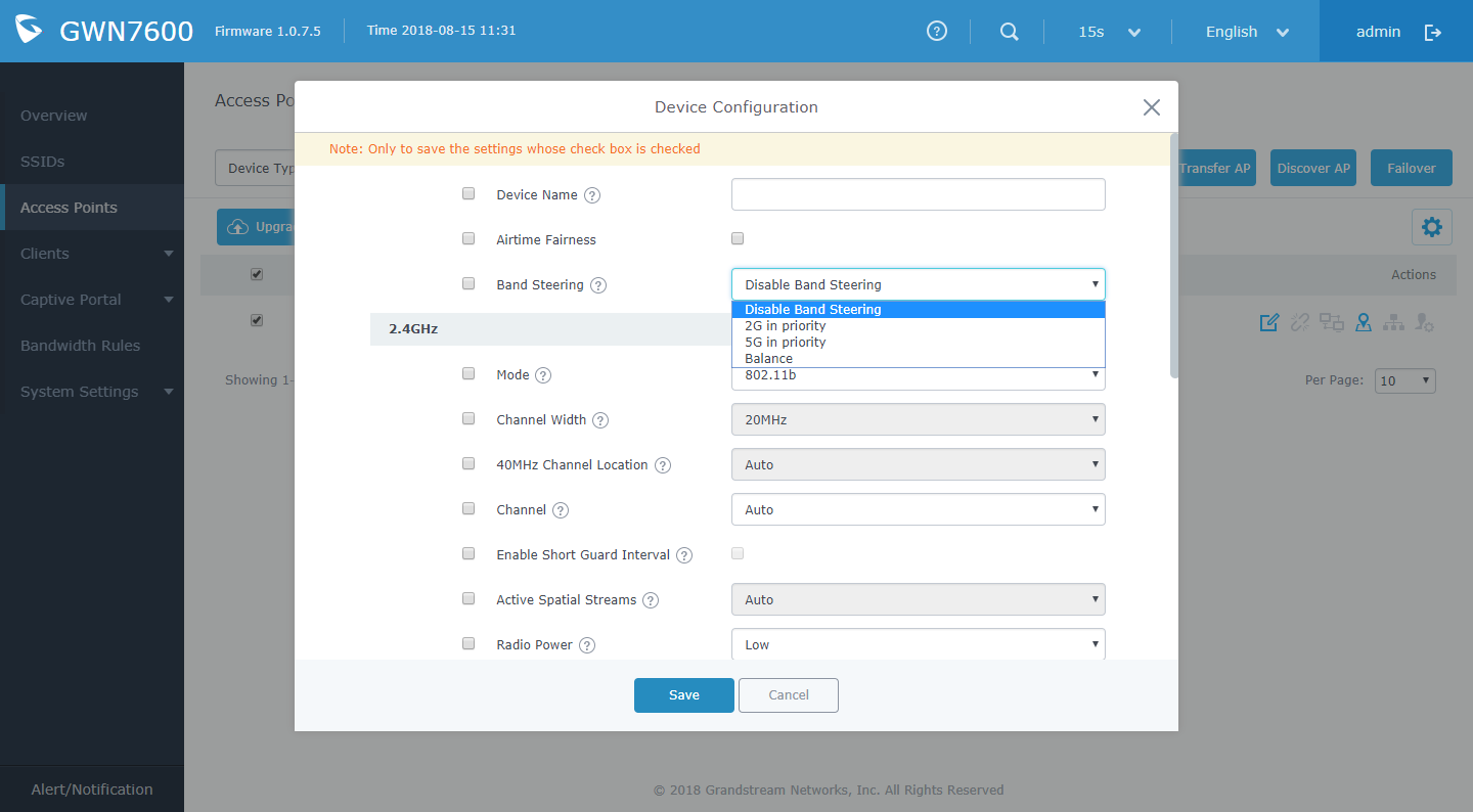
Band steering functions are divided into three items. Go to Access Points->configure to configure it.
- 2G in priority, lead the dual client to the 2G band
- 5G in priority, the dual client will be led to the 5G band with more abundant spectrum resources as far as possible
- Balance, access to the balance between these 2 bands according to the spectrum utilization rate of 2.4G and 5G.
CISCO MERAKI
Wireless Configuration
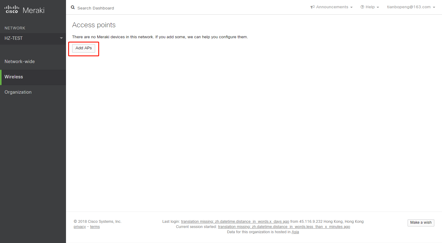
- Find the Dashboard “network” to which you plan to add your APs, or create a new network.
- Add your APs to your network.
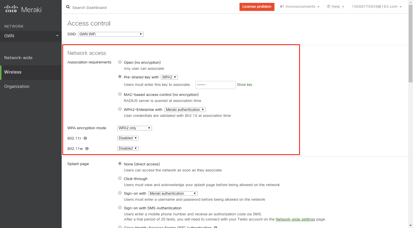
- Make any additional configuration changes under the Configure section of Dashboard network. Please make sure to review SSIDs, Access Control, Firewall & Traffic Shaping configuration pages.
Band Steering
Go to Wireless->Access control->Wireless options.
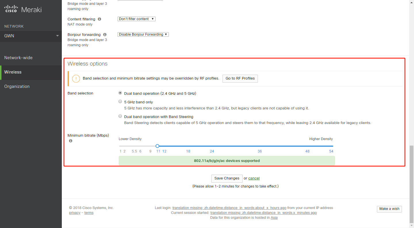
Band selections are:
- Dual band operation: 2.4GHz and 5GHz
- 5GHz band only: 5GHz has more capacity and less interference than 2.4GHz, but legacy clients are not capable of using it.
- Dual band operation with Band Steering: Band Steering detects clients capable of 5 GHz operation and steers them to that frequency, while leaving 2.4 GHz available for legacy clients.
ARUBA CENTRAL
Wireless Configuration
The app selector lists the apps available for the Managed Service Portal portal users. The Wireless Configuration app allows you to configure SSIDs, radio profiles, security and firewall settings, and enable services on Instant APs. It also allows you to configure Instant APs provisioned under template groups through configuration templates.
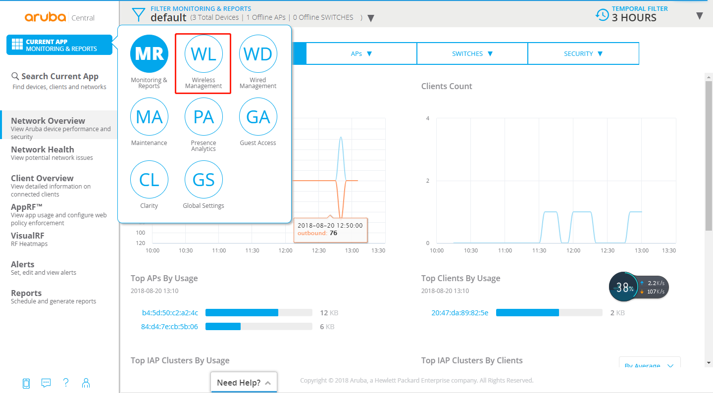
To configure WLAN settings, complete the following steps:
- From the app selector, click Wireless Management.
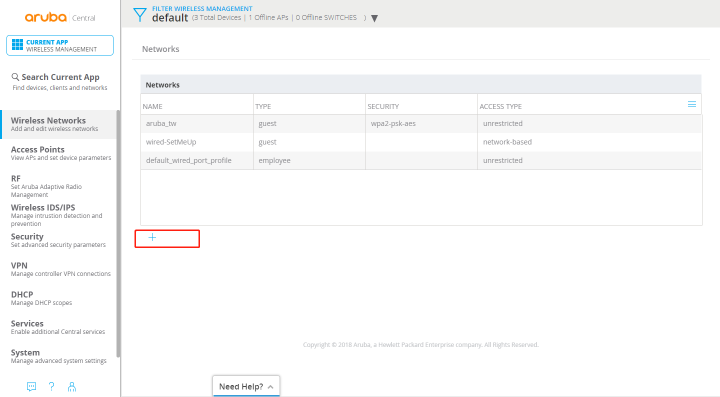
- From the group selector, select a group or a device.
- On the left navigation pane, click Wireless Networks. The Wireless Networks page opens.
- To create a new SSID profile, click the + icon. The Create a New Network pane opens.
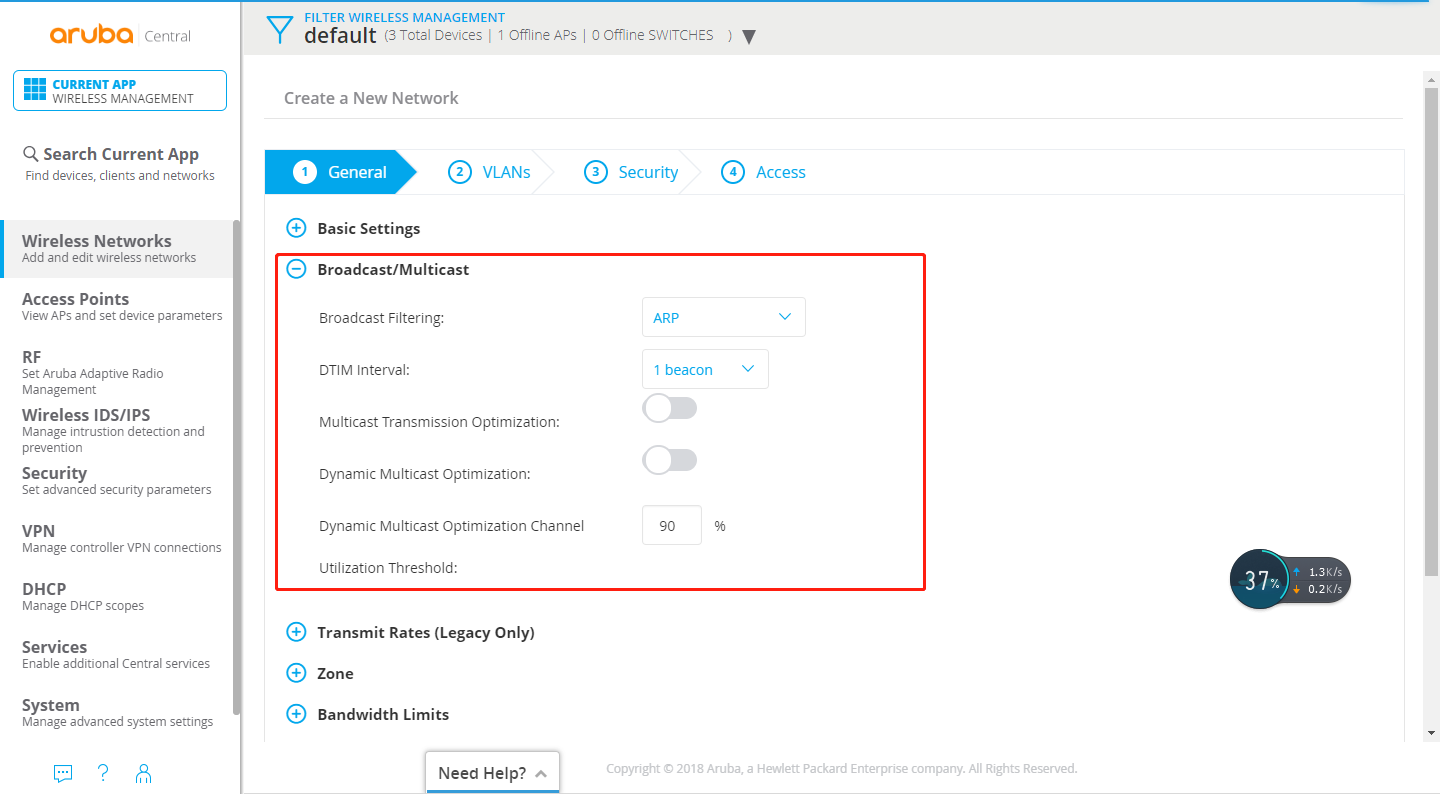
- Configure Broadcast Filtering. Select any of the following values:
- All. The Instant AP drops all broadcast and multicast frames except DHCP and ARP, IGMP group queries, and IPv6 neighbor discovery protocols.
- ARP. The Instant AP drops broadcast and multicast frames except DHCP and ARP, IGMP group queries, and IPv6 neighbor discovery protocols. Additionally, it converts ARP requests to unicast and sends frames directly to the associated clients.
- Disabled. All broadcast and multicast traffic is forwarded to the wireless interfaces.
- Configure DTIM interval.
The DTIM Interval indicates the DTIM period in beacons, which can be configured for every WLAN SSID profile. The DTIM interval determines how often the Instant AP delivers the buffered broadcast and multicast frames to the associated clients in the power save mode. The default value is 1, which means the client checks for buffered data on the Instant AP at every beacon. You can also configure a higher DTIM value for power saving.
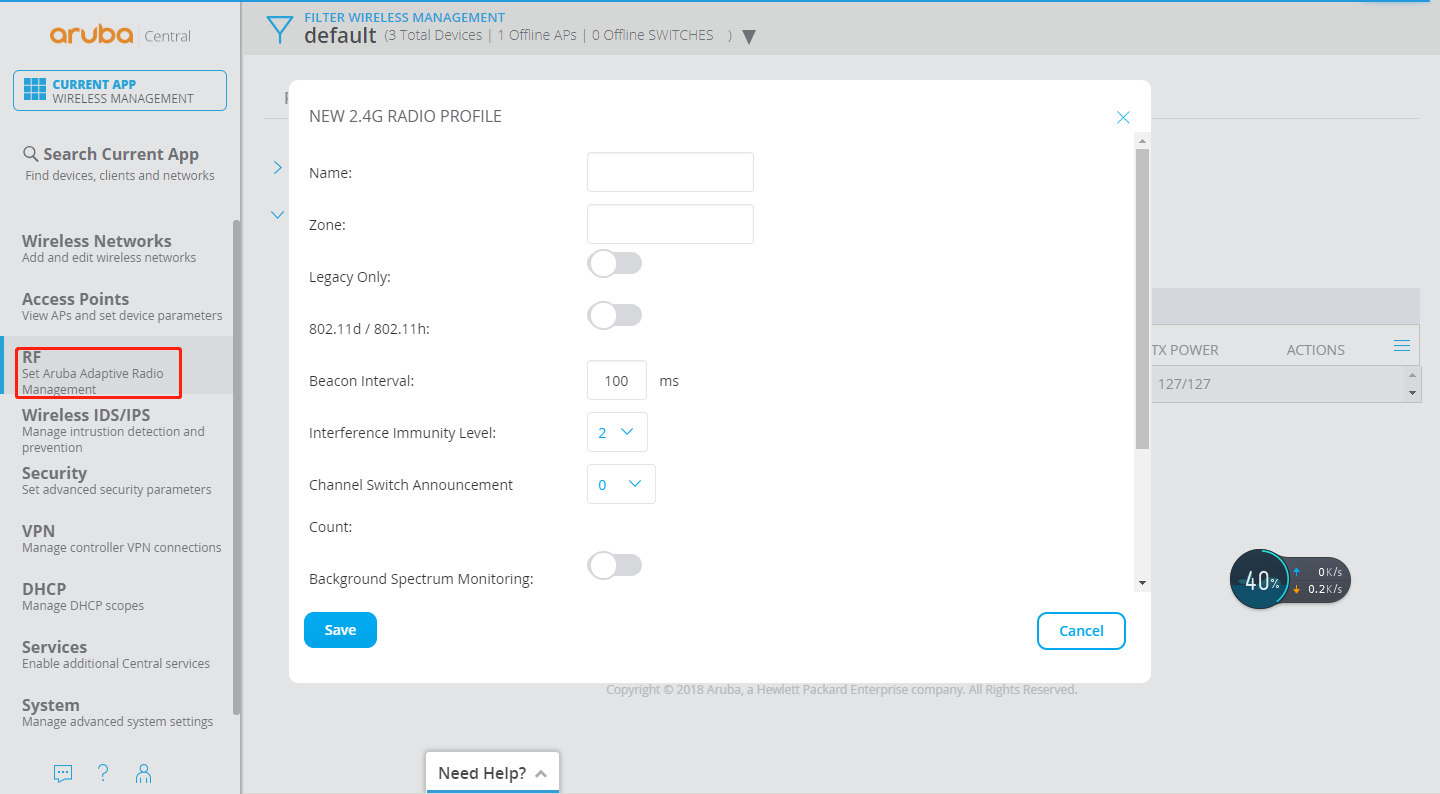
- Configuring Radio Parameters
To configure RF parameters for the 2.4 GHz and 5 GHz radio bands on an Instant AP, complete the following steps:
- From the app selector, click Wireless Management.
- From the group selector, select a group or a device.
- On the left navigation pane, click RF. The RF page opens.
- Click Radio.
- Under 2.4 GHz, 5 GHz, or both, configure the parameters.
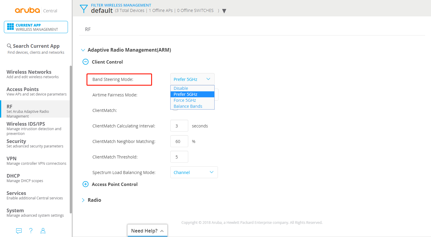
Band Steering
To configure ARM features such as band steering, and airtime fairness mode and Client Match, complete the following steps.
- From the app selector, click Wireless Management.
- From the group selector, select a group or a device.
- On the left navigation pane, click RF. The RF page opens.
- Under Adaptive Radio Management (ARM), click Client Control.
- For Band Steering Mode, configure the parameters.
RUIJIE CLOUD
Wireless Configuration
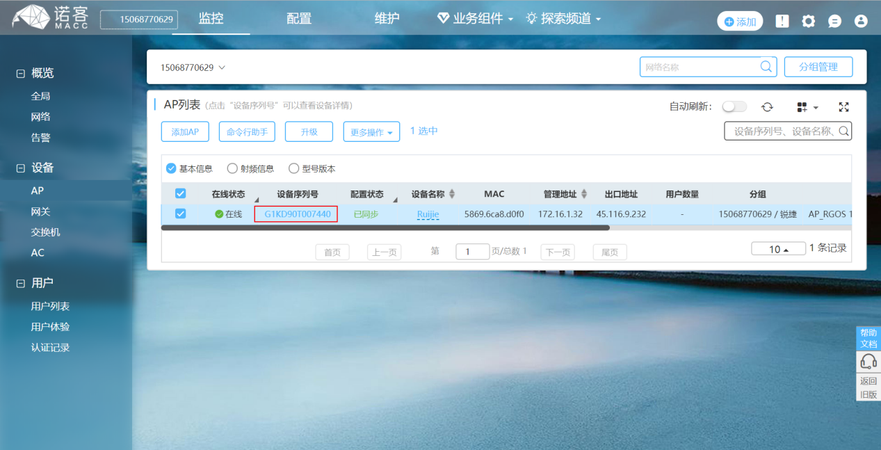
Create new network & add APs.
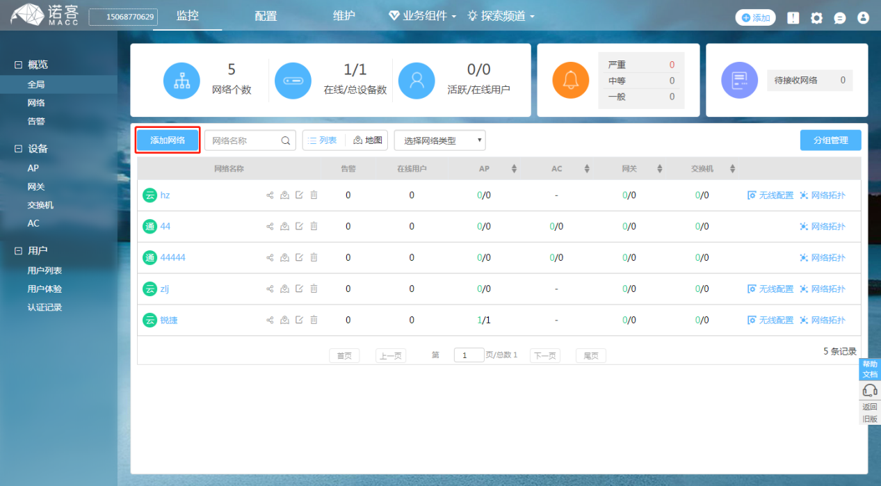
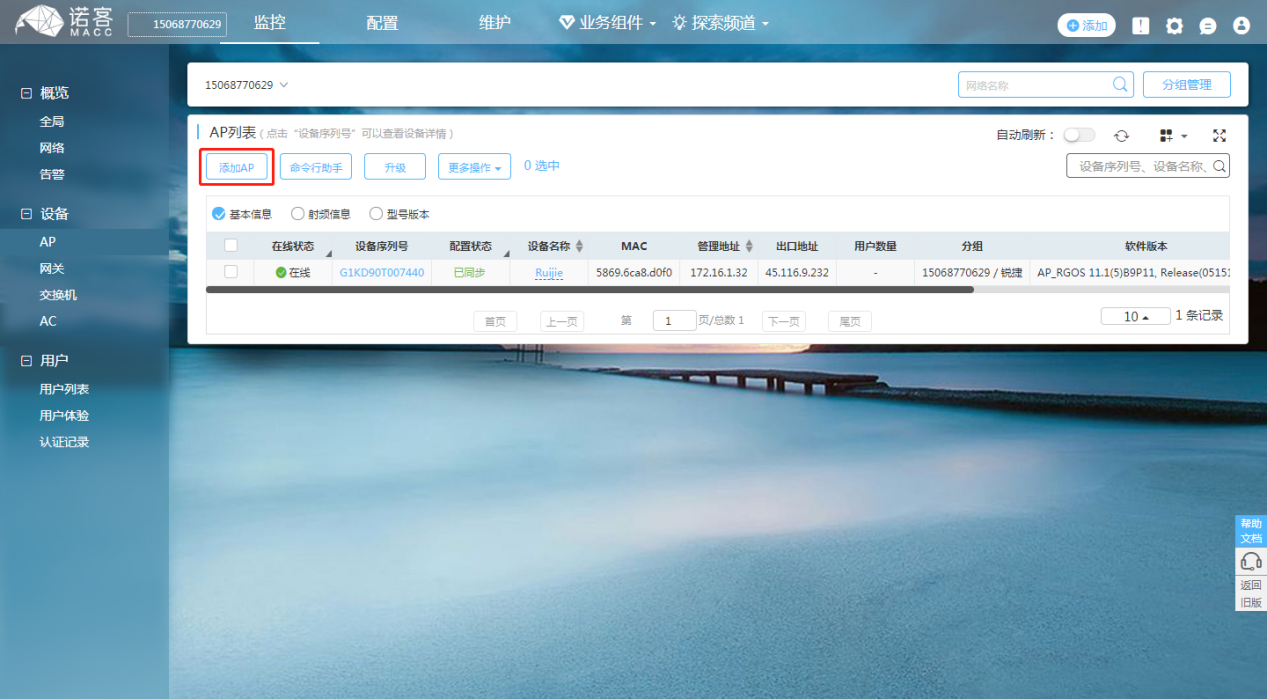
All AC device information under the current account can be viewed in the monitoring – device -AC to see whether the device is online and whether the configuration status of the device is synchronized.
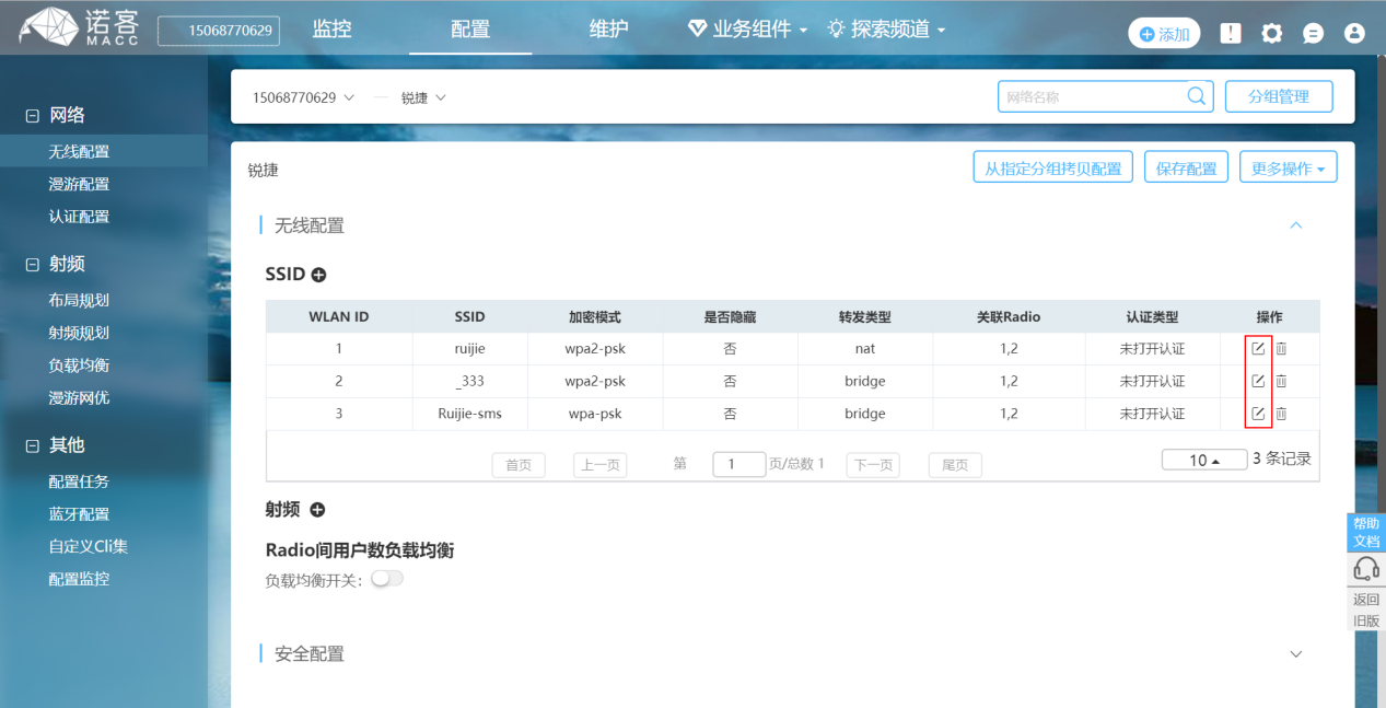
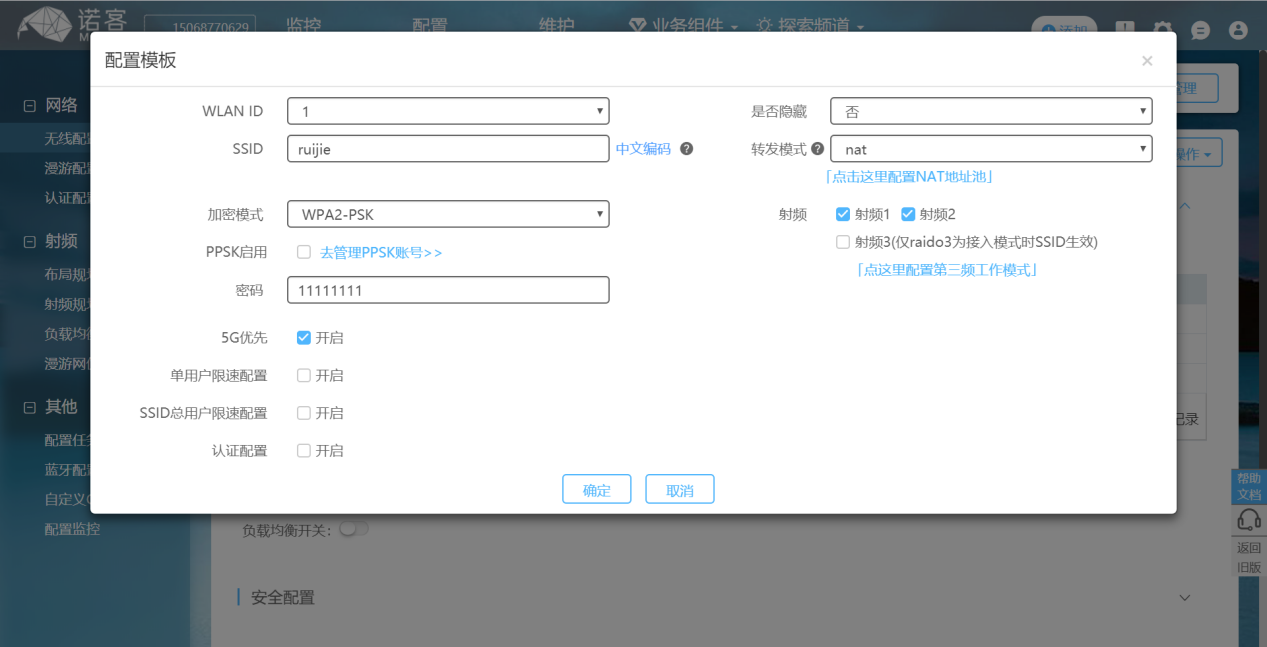
If the wireless configuration needs to be modified, the following steps can be followed: configuration -> wireless configuration.
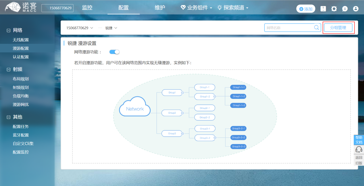
If the roaming function is turned on, users can achieve seamless roaming within the network scope.
Band Steering
5G priority: after 5G priority is turned on, AP will guide the wireless terminals supporting 5G to have priority access to 5G frequency band, reducing the pressure of 2.4g frequency band.
UBIQUITI UNIFI
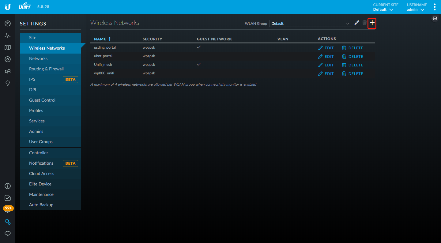
Wireless Configuration
- To add a new WLAN group, click + button.
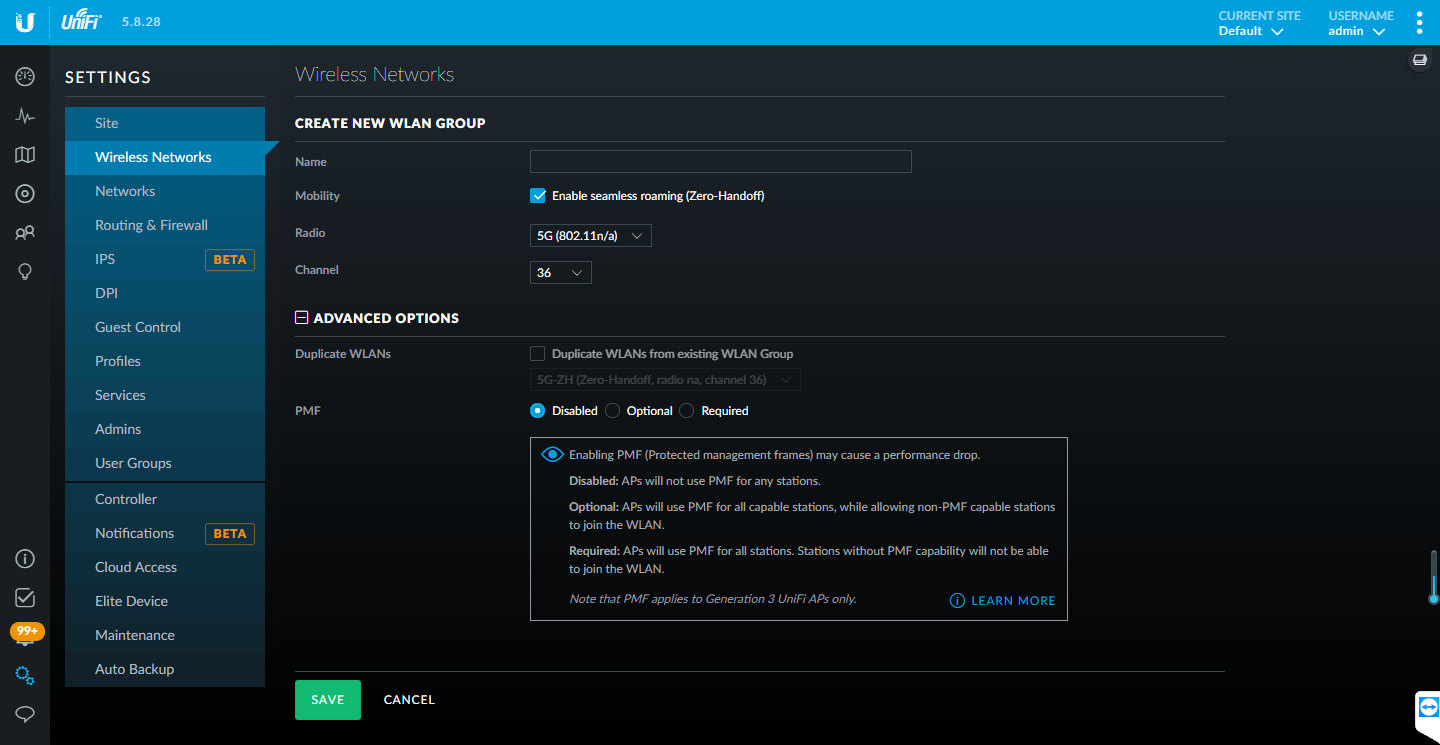
- Add or Edit a WLAN Group.
Name: Enter or edit a descriptive name for the WLAN group.
Mobility: To enable seamless roaming (Zero Handoff), select the checkbox.
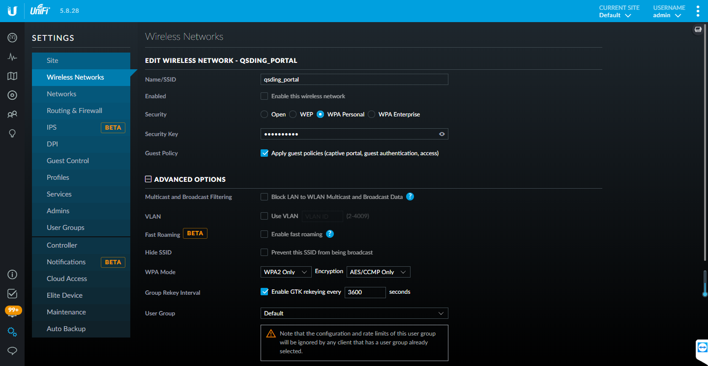
- Create or Edit a Wireless Network.
- Name/SSID: Enter or edit the wireless network name or SSID.
- Enabled: Select this option to make the network active.
- Security: Select the type of security to use on your wireless network.
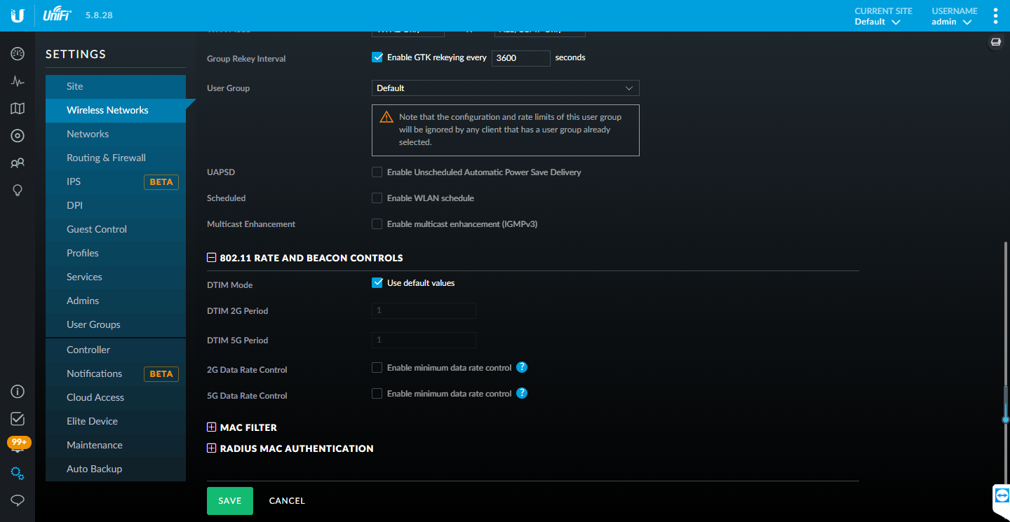
- DTIM Mode:
Select this option to use the default DTIM (Delivery Traffic Indication Message) values. Increasing the DTIM values allows devices to conserve power, at as light latency penalty. Deselect it to configure the values below.
- DTIM 2G Period: Enter the number of beacons between the 2.4 GHz DTIM beacons. The default is 1.
- DTIM 5G Period: Enter the number of beacons between the 5 GHz DTIM beacons. The default is 1.
- 2G Data Rate Control: Select this option to determine what bit rates your 2.4 GHz network will allow. Disabling lower bit rates can improve performance for higher density networks but will make some older devices in compatible with your network and limit the range of your wireless network.
- 5G Data Rate Control: Select this option to determine what bit rates your network will allow. Disabling lower bit rates can improve performance for higher density networks but will make some older devices incompatible with your network and limit the range of your wireless network.
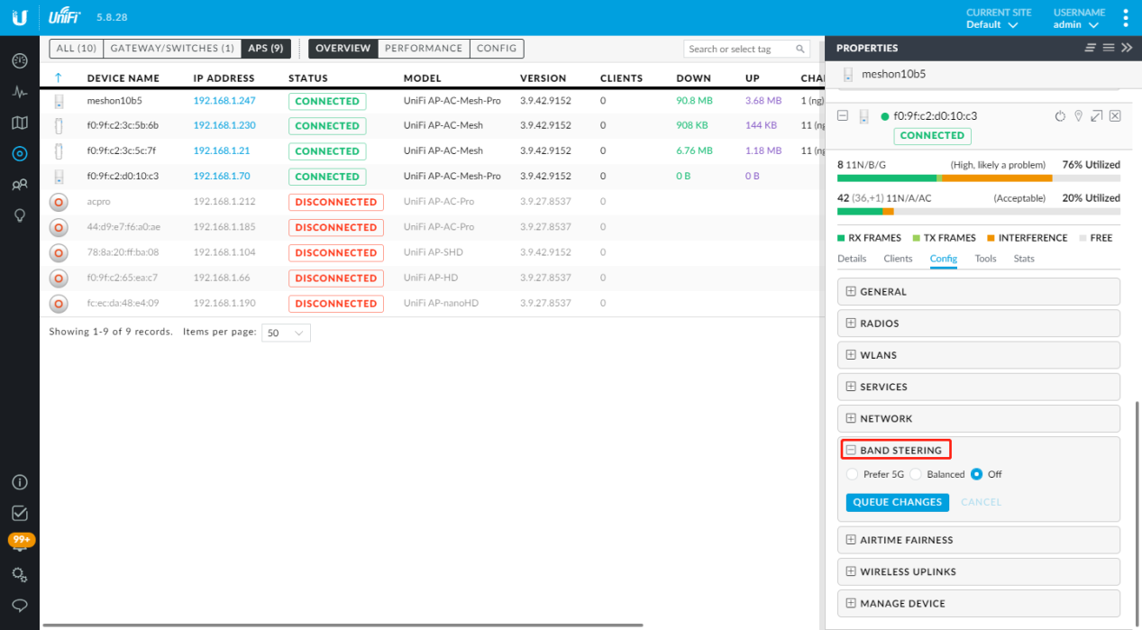
Band Steering
The Devices screen displays a list of UniFi devices discovered by the UniFi Controller. You can click any of the column headers to change the list order.
MIST
Wireless Configuration
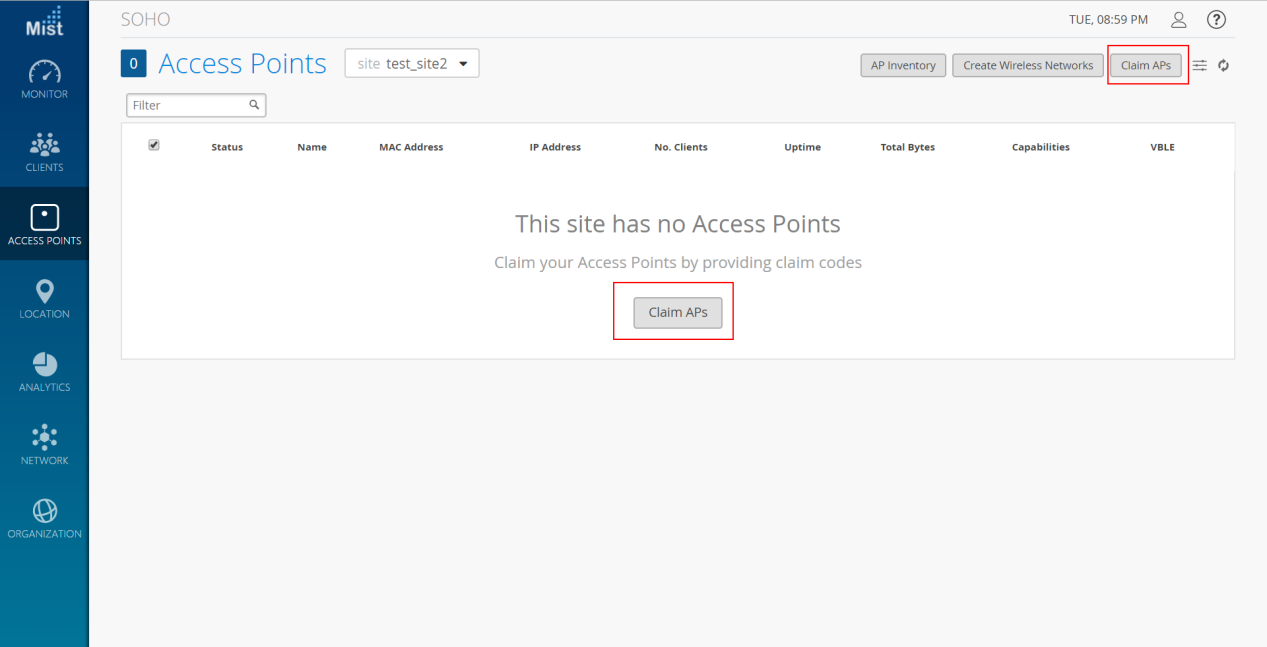
- Claim the AP.
Click on Access Points on the left-hand navigation bar. If you have a claim code for the AP, enter it by clicking the Claim APs button in the top right of the Access Points screen. Then, fill in the code and click the Claim button to add the AP. After that, click to select the new AP in the list and enter a name in the Name field.
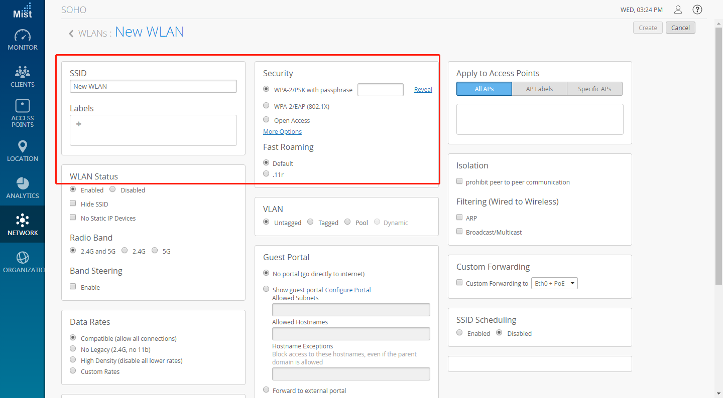
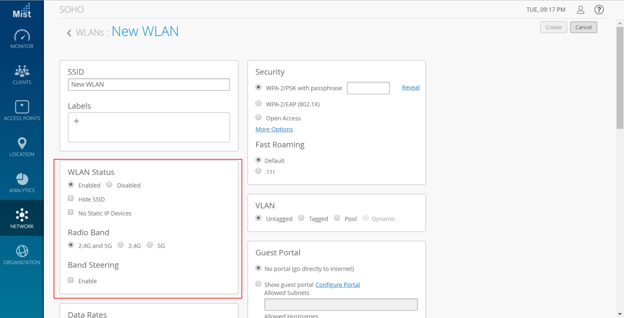
- Setting up a WLAN
Click on Networks on the left-hand navigation bar, then select WLANs. Select appropriate options for WLAN Status.
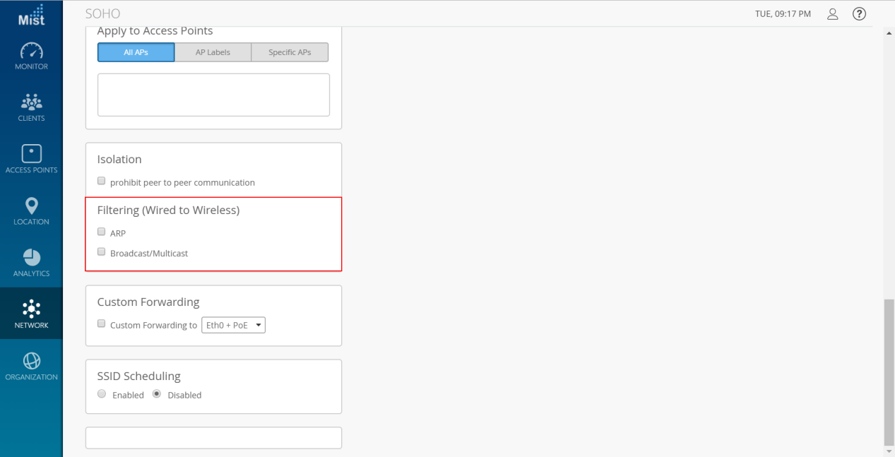
- Filtering
By default Mist supports Proxy ARP.
- ARP Filter: When ARP filter is enabled, we block all ARP broadcast requests from going to the specified wireless Interface. When ARP filter Is disabled, Proxy ARP will try to resolve the Ethernet address of requests, and if not known, will flood the original request to any Interface not being ARP filtered.
- Broadcast / Multicast Filter: When Enabled, this filter will BLOCK ALL Broadcast and Multicast packets on a specified Interface, except:
a) ARP’s (as handled above)
b) DHCP broadcast transactions.
c) IPv6 Neighbor discovery frames. (ICMPv6).
All other broadcasts will we blocked, including IPv6 Broadcasts/Multicasts, and ALL MDNS frames. (IPv4 & IPv6)
- Allow MDNS Checkbox: This option ONLY has any effect when #2 (the Broadcast / Multicast filter is ENABLED). When selected, this option will ALLOW mDNS packets to transmitted through the specified interface. This includes IPv4 and IPv6 mDNS. If Not selected, then the Broadcast/Multicast filter will treat mDNS frames just like any other broadcast/multicast frame, and block them.
Band Steering
Enable Band steering under Network -> WLANs. Make sure both 2.4GHz and 5GHz radios are enabled on your WLAN to be able to use Band Steering mode.
EZMASTER
Wireless Configuration
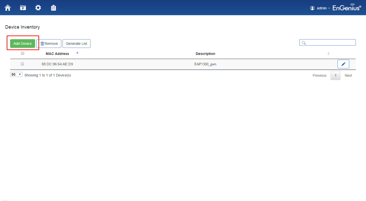
- Adding devices to ezMaster Device Inventory.
Enter the MAC Address, Check Code and Description of the device you want to register.
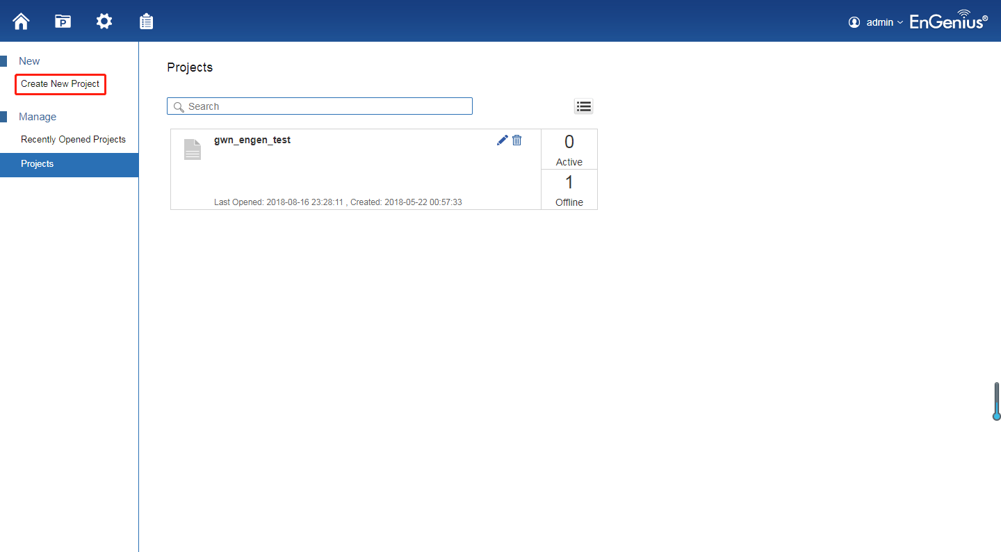
- Managing devices using ezMaster.
In order to start managing and monitoring Neutron devices, these devices must first be added to a project. Make sure that your Neutron device is connected to a network with a DHCP server and can access the Internet. Click on the Project icon to create a new project.
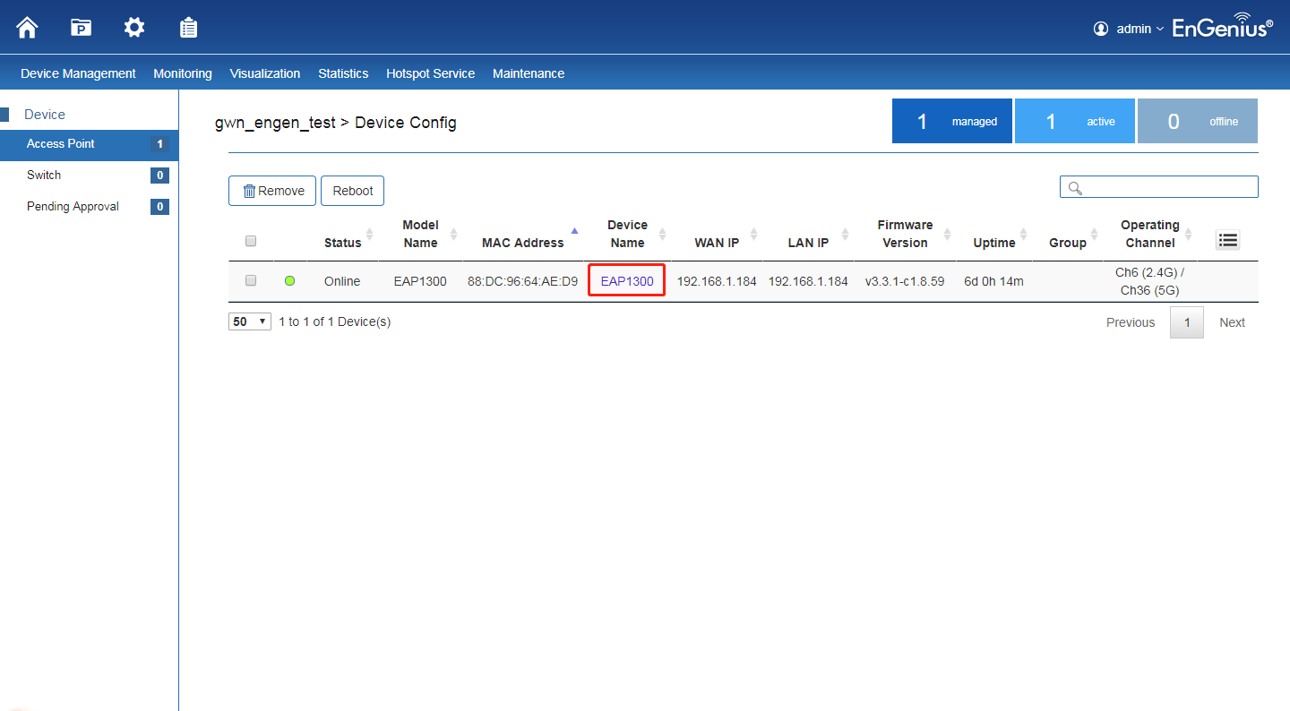
- Device Configuration
Once the AP is online (green), to configure your AP, click on the Device Name link of your AP to bring up the configuration menu.
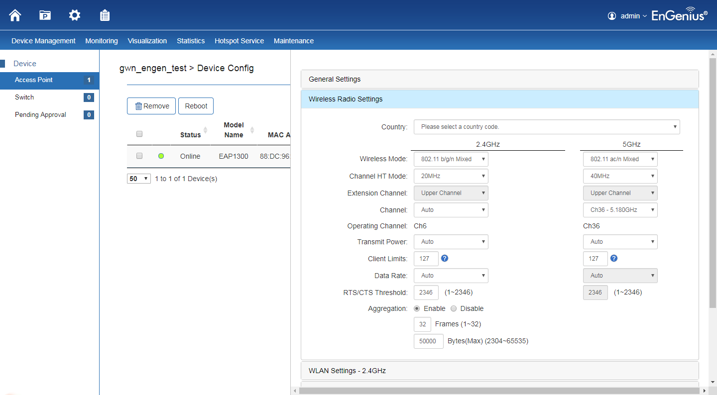
- Set Wireless Radio Settings.
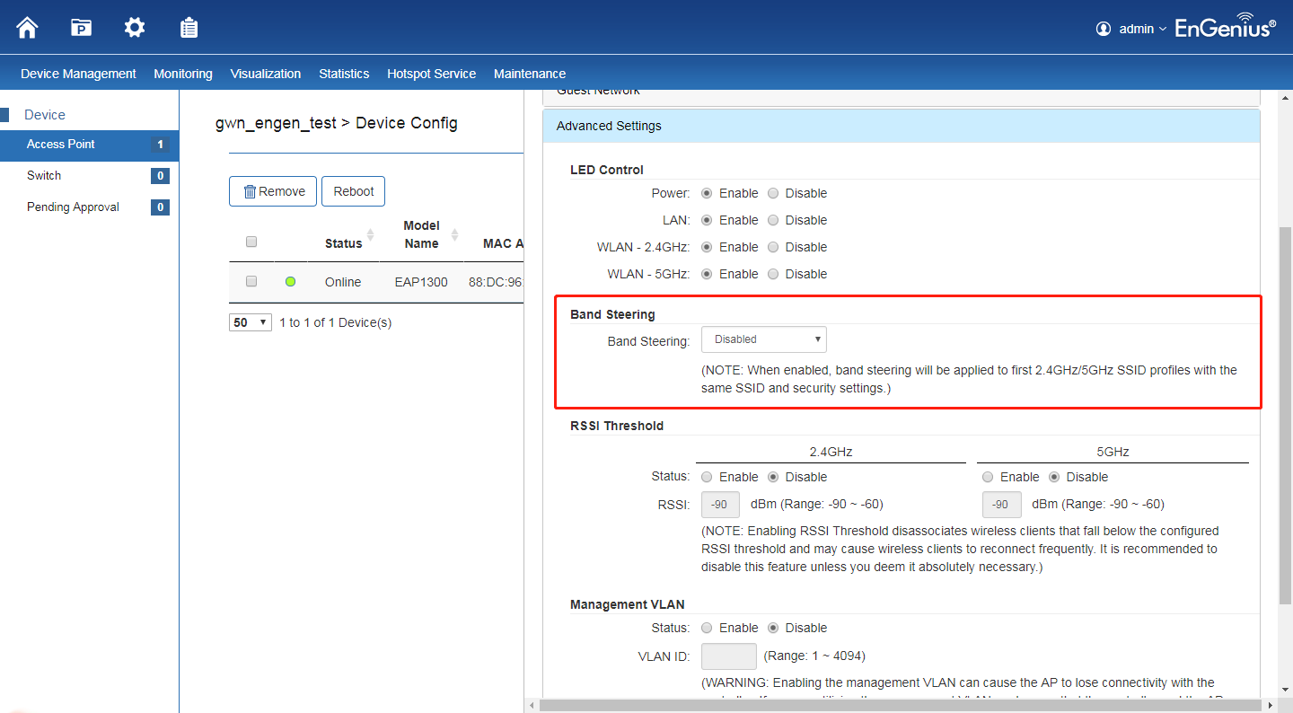
Band Steering
When “Band steering” is enabled, when the wireless client first associates with the AP, the AP will detects whether or not the wireless client is dual-band capable, and if it is, it will force the client to connect to the less congested 5GHz network to relieve congestion and overcrowding on the mainstream 2.4GHz frequency. It does this by actively blocking the client’s attempts to associate with the 2.4GHz network.
CLOUDTRAX
Wireless Configuration
- Create a new network. Fill in below information.
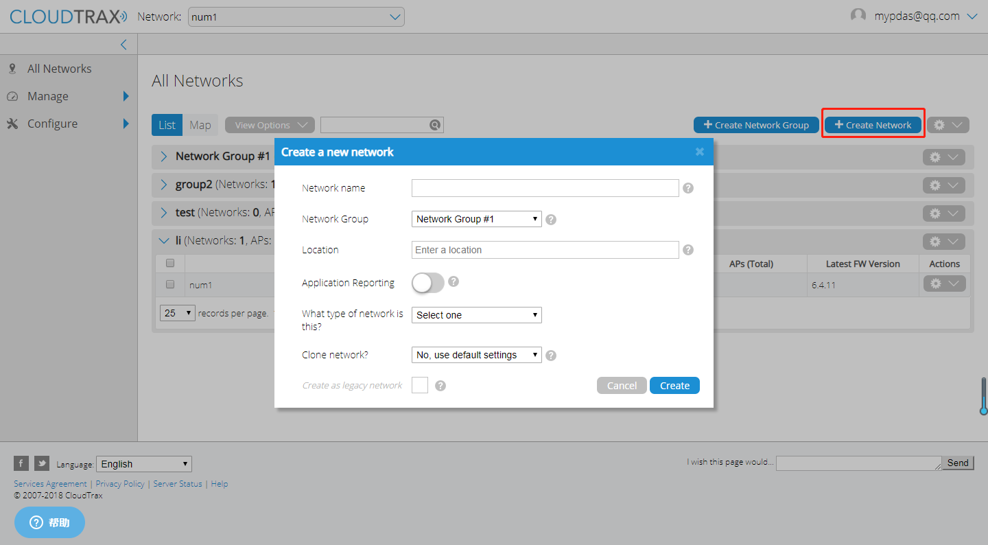
- Network name: This is the name you want to give this specific network. You will use this name to make changes to the network, display reports, etc.
- Network Group: This determines which user accounts will administrate this network.
- Location: Enter a street address for the first access point. To add access points, you will be shown a map that you click on to place access points. By entering an address here, you will be centered on the correct location for your network.
- Application Reporting: This will set whether the Application Reporting function is enabled by default on this network, which will provide more in depth reporting on the sort of traffic on your network.
- Network Type: This gives us an idea how you are using CloudTrax so we can find more ways to improve.
- Clone Network?: If you wish to carry over your network settings from an already existing CloudTrax network under your same account, you can choose to clone that networks’ settings here.
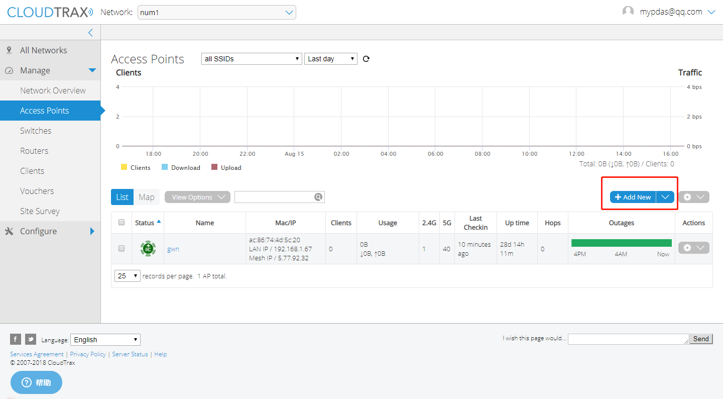
- Add access points to your network
Navigate to the Manage->Access Points screen. There are three options to add access points to your network: click the “Add New” button to add access points one at a time by clicking on a map, or use the down arrow to the right of that to add access points in bulk.
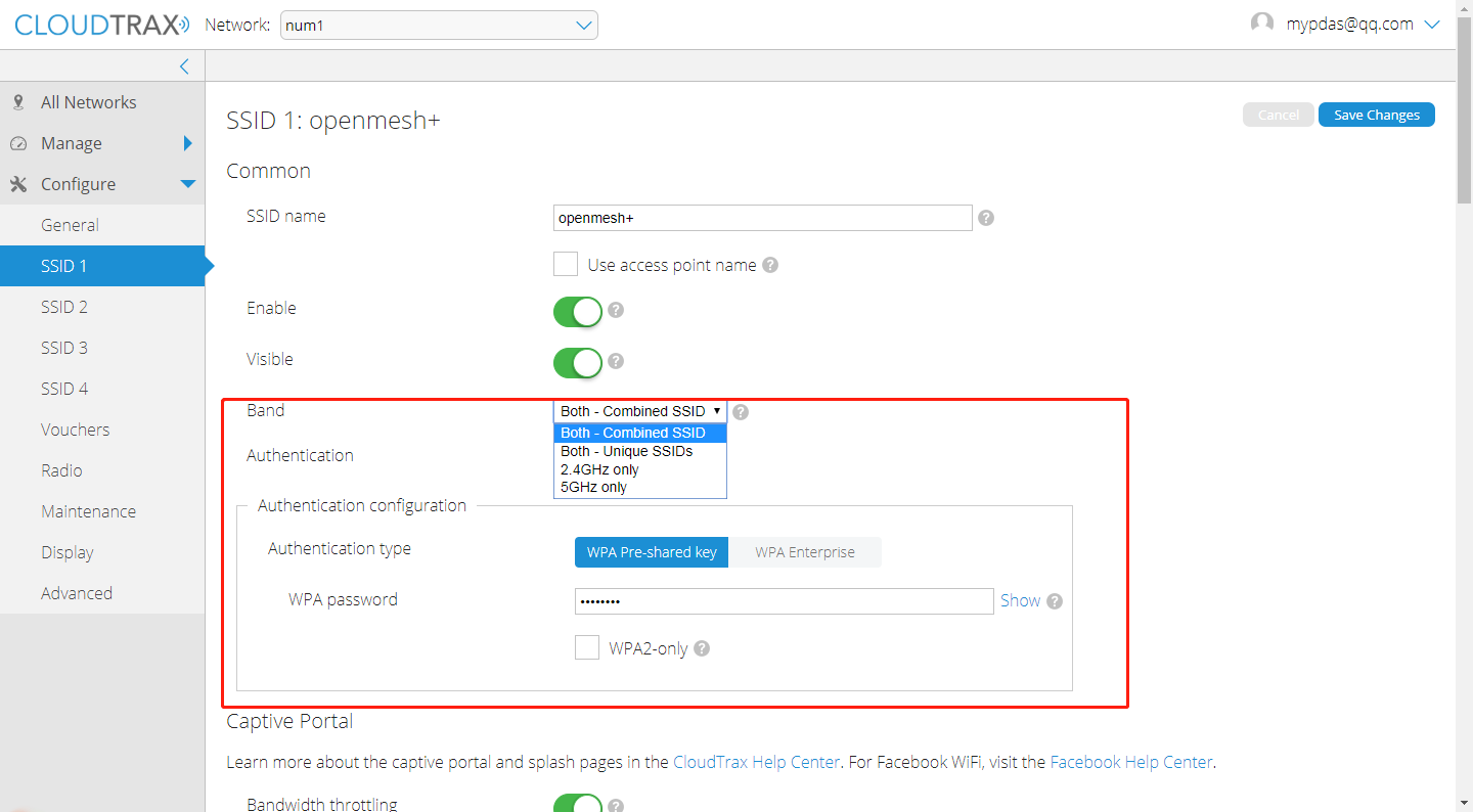
- Configure your network
Each CloudTrax device can broadcast four unique SSIDs that users can connect to. Each of these SSIDs are controlled independently in CloudTrax. Typically users have a mix of public SSIDs – with splash pages, bandwidth throttling, DNS filtering and client isolation – and private SSIDs, with WPA Enterprise authentication and access to LAN resources and other clients. When we created your network, we set the first SSID to be public and the second SSID to be private, but you can adjust these any way you wish.
TP-LINK
Wireless Configuration
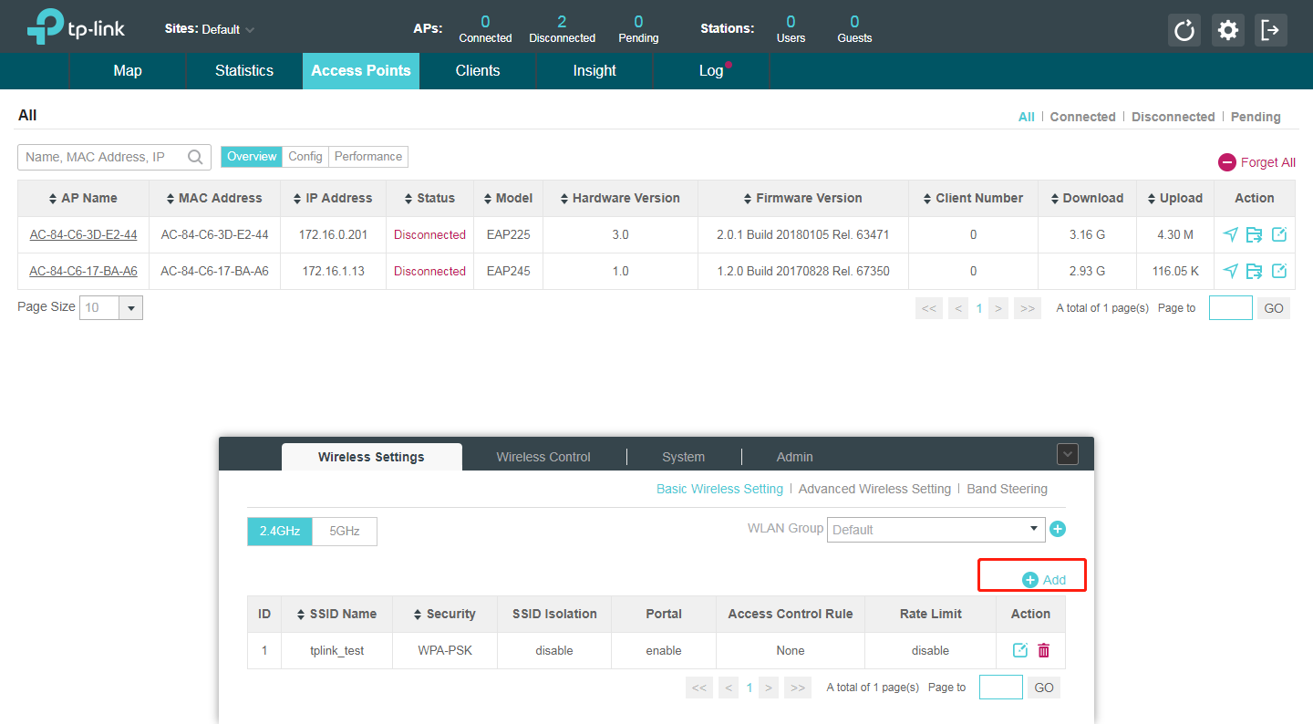
- Add Wireless Networks
Select a band frequency and click + to add a WLAN group.
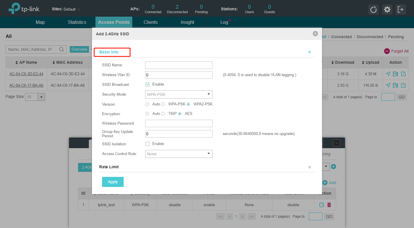
- Add an SSID to the specific WLAN group, Configure the parameters in the following window.
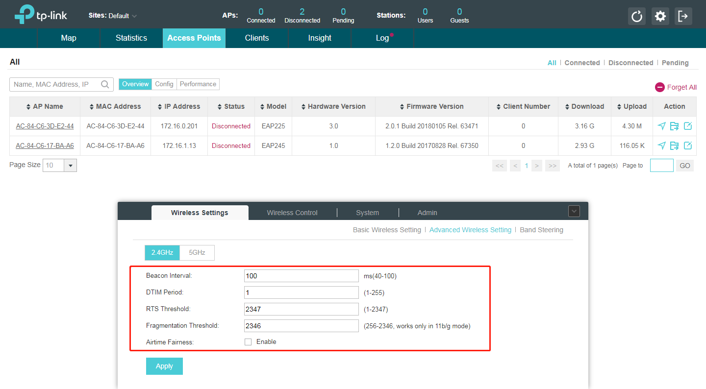
- Configure Advanced Wireless Parameters
The advanced wireless parameters consist of Beacon Interval, DTIM Period, RTS Threshold, Fragmentation Threshold and Airtime Fairness. Go to Wireless Settings->Advanced Setting.
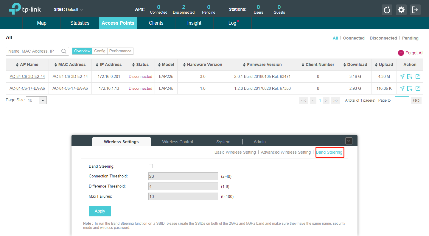
Band Steering
A client device that is capable of communicating on both the 2.4GHz and 5GHz frequency bands will typically connect to the 2.4 GHz band. However, if too many client devices are connected to an EAP on the 2.4 GHz band, the efficiency of communication will be diminished. Band Steering can steer clients capable of communication on both bands to the 5GHz frequency band which supports higher transmission rates and more client devices, and thus to greatly improve the network quality. Go to Wireless Settings > Band Steering.